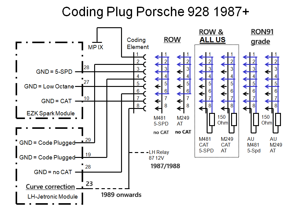
The above diagram is for a 1987/1988 model. Pin 8 is not used for anything regarding coding. However, pin 8 is connected to LH relay pin 87 which means it carries 12v when the Relay is active and injectors are powered.
This changed in 1989. The new wiring look was introduced and a new feature was installed: the Ignition Monitoring relay (IMR). In case of an ignition failure the IMR shuts down power to a group of cylinders to avoid fueling without ignition. To make sure the engine can still idle and ignore the Lambda sensor, a 150 Ohms resistor was introduced so that when the LH knows that the IMR is active, it uses a fixed value for cure correction (LH pin 23) .
When the IMR becomes active the AL signal of the IMR becomes ground, which grounds pin 6 of the coding element, which tells pin 28 of the LH that it is in non-CAR configuration and the 150Ohms resistor sets a base value for the LH to simulate a CO potentiometer as used in non-CAT S4 models.
So starting 1989 model the diagram below is applicable: