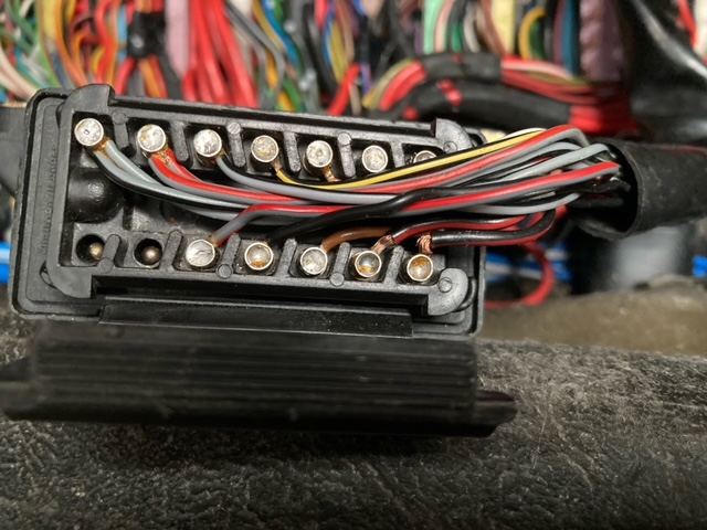
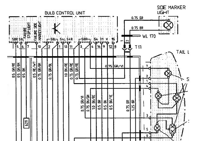
Wired detached from connector 1990 ROW
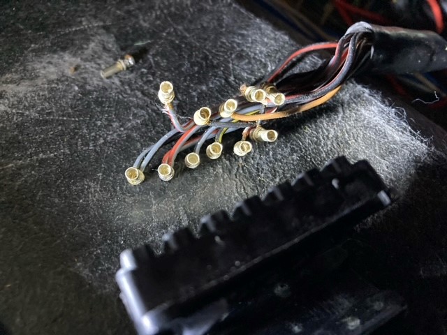
Wire color codes at this connector (the number in parentheses indicates the
number of wires attached to the pin):
Code:
(1) BK/RE 14 13 (1) BK/RE
(1) BK 12 11 (1) BK/RE
(1) RE/WT 10 9 (1) BR
(1) BK/YE 8 7 (1) BK
(1) GR/BK 6 5 (1) GR/RE
(2) GR/VI 4 3 (2) GR/RE
(2) GR/BK 2 1 (2) GR/BL
BK=black; WT=white; RE=red; GN=green; YE=yellow; GR=gray; BR=brown; BL=blue;
VI=violet; PK=pink
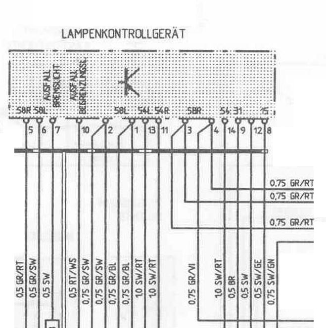
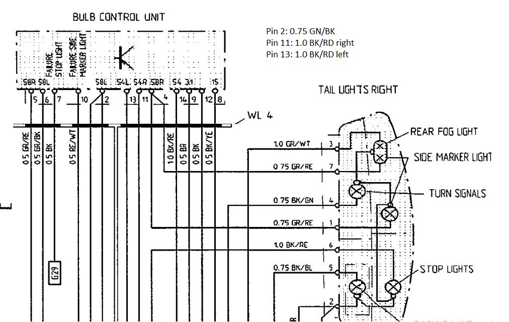
Pin functions/connections (standard terminal designations are in parentheses at
the end of each description, where known/appropriate):
1: outer two marker lamps in left tail light assembly (58L)
2: left side marker lamp and middle marker lamp in left tail light assembly
(58L)
3: right side marker lamp and middle marker lamp in right tail light assembly
(58R)
4: outer two marker lamps in right tail light assembly (58R)
5: front right side marker lamp, front right corner marker lamp, fuse, light
switch (58R)
6: front left side marker lamp, front left corner marker lamp, fuse, light
switch (58L)
7: "stop/brake lamp" failure (to instrument cluster)
8: ignition power (15)
9: ground (31)
10: "parking/marker lamp failure" (to instrument cluster)
11: right brake/stop lamp (54R)
12: fuse to X-bus (accessory/ignition power, but not during start) (X)
13: left brake/stop lamp (54L)
14: brake/stop signal (54)
Schematic 1988 S4 (US?)
1991 S4 ROW
1991 S4 (US version)
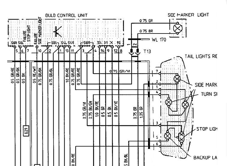
1993 GTS US version
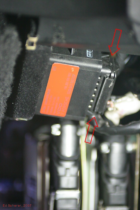
the bulb controller has a 14 pin connector but there is a difference for US
and ROW models:
The US has 14 wires connected where the ROW model has 12 wires connected.
Yes, Pin 11 and 13 both have an identical wire. If you want to be sure, you need to measure the resistance on the wires when one stop light bulb is removed. That will show you which is left (and right).
Pin 1 and 3 are not used in the ROW model, they are for the additional
side marker lights in the US model.