Made some progress this weekend on
the cruise brains. I've started a new thread instead of adding it to 3 plus
pages of the last one.
First off, thanks to James Mahaffey, a MB affectionato, we now have a
description of a similar, although not identical VDO cruise circuit.
The 10-pin connector is actually a 12-pin connector with pins 1 and 2 blanked
off.
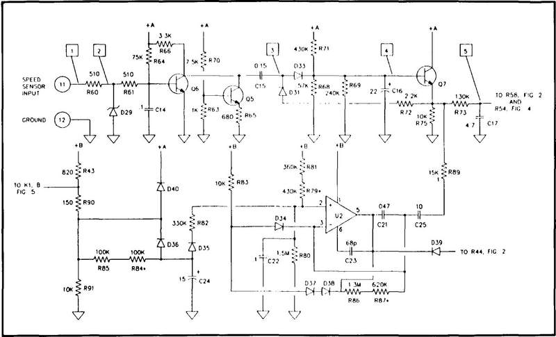
The speed-sensing portion of the cruise control circuit is shown in Figure 1.
Test points are indicated by boxed numbers. This wave is observable at point 1,
is then half-wave rectified (point 2). The signal is then amplified and limited
by Q5 and Q6, giving a
rectangular wave of 6 volts at point 3. At point 4 the wave is a 0.1 to 0.2-volt
ripple. The signal is converted to a DC voltage, varying linearly with respect
to the frequency of the speed sense signal, observable at point 5. R69 trims the
sensitivity.
Voltage Comparison
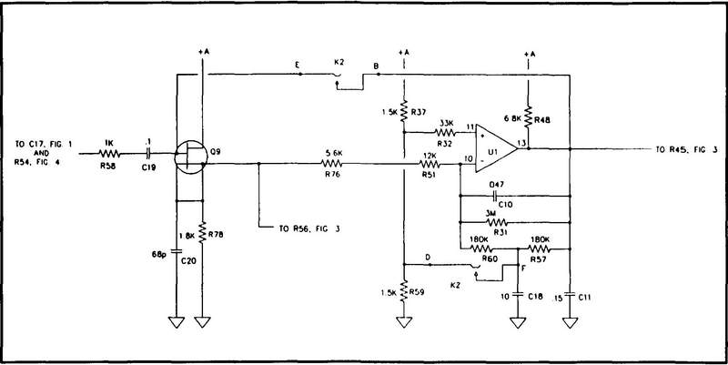
The voltage generated in the speed-sensor circuit is captured on capacitor C19
when you set the cruise control by engaging the Accelerate Set or Decelerate Set
controls (see Figure 2). In the engaged condition, the output of Q9, a dual-gate
FET riding C19, becomes the standard voltage against which the car's throttle is
controlled through a servo-amplifier. An Accelerate Set signal latches down
relay 2 (K1 in Figure 5), overriding the controller, opening the throttle and
connecting C19 directly to the speed sensing-circuit. A Decelerate Set command
does the same except that the output current is turned off, closing the
throttle. A Cancel command disengages the controller by dropping the latch of
relay 1 (K1 in figure 5), but the charge on C19 is preserved. Setting Resume
relatches K1, and pressing the brake pedal unlatches KI. The standard DC voltage
is amplified by a section of the quad comparator, U1, connected as an op amp.
R76 trims the servo gain.
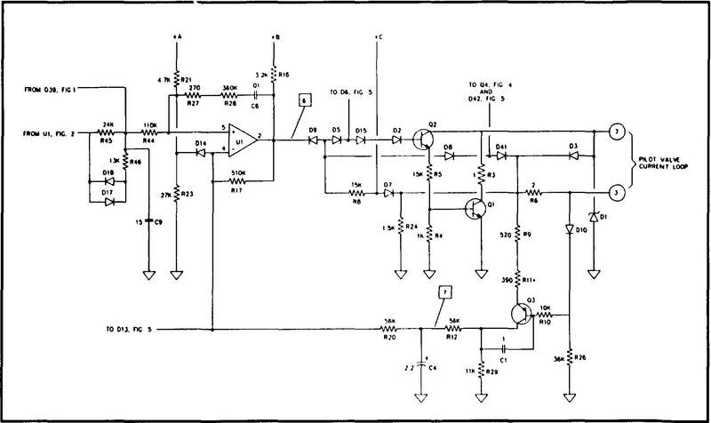
Another part of U1 is connected as a multivibrator, as shown in Figure 3. The
amplified DC voltage controls the pulse length of this oscillator, observable as
a rectangular pulse train 7 volts high at point 6. The oscillator output is
converted to a current of 100-300 mA, on pins 7 and 3, by Q2 and the final
driver Q1. The current is used to drive a pilot valve controlling a
vacuum-diaphragm actuator connected to the throttle. Voltage indicative of the
average current produced by Q1 is observable at point 7. Q3 is the
current-to-voltage converter, providing a negative feedback stabilizer to the
multivibrator. R27 trims the multivibrator switching decay rate, and R11 trims
the negative feedback.
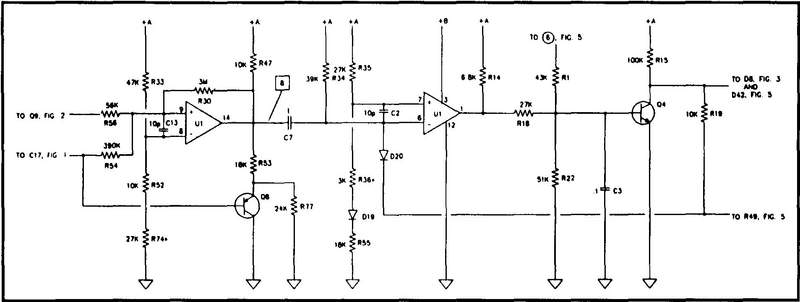
A third section of U1 is connected as a Schmitt trigger, as shown in Figure 4.
If the car's speed drops to 10 MPH below the "stored" speed (standard voltage),
the Schmitt trigger fires, giving a negative pulse observable at point 8. The
pulse, amplified and inverted by the
fourth section of U1 and Q4, causes K1 to unlatch, dropping control of the
throttle. This condition is perfectly normal and is particularly noticeable in a
diesel on a steep climb. Another normal drop-out condition is a speed below
about 12 MPH. When the standard voltage (charge on C17) drops to 1.0 volt, Q8
conducts, grounding the negative input to the latchout amplifier, as would the
Schmitt-triggered negative pulse. R74 trims the Schmitt trigger threshold, and
R36 trims the latchout amplifier gain.
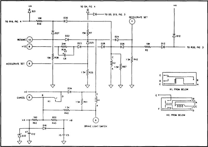
Figure 5 shows the relays and the diode logic array for the four cruise control
switches; all four are momentary switches. A Decelerate Set command connects pin
4 to +12 volts. Accelerate Set connects pin 9 to + 12 volts. Pin 10 is connected
to +12 volts upon Resume, and pin 8 is always at +12 volts except momentarily
upon the Off command. Pin 6 is connected to the brake light, with K1 grounded
through the light unless the brake pedal is pressed.
The next step was building a test
bench to fake the amp into thinking it was running.
I used a dpdt spring loaded switch to operate the set/resume function, and a
spst switch for the cancel function. The common connector of each was tied to
+12 v. The set line runs to pin 9, the resume to pin 10 and cancel to pin 8. To
cancel, 12 v is momentarily disconnected from pin 10. The brake switch pin (pin
6) is grounded.
Pins 3 and 7 provide output current to the vacuum actuator. I connected a low
value resistor between these lines to monitor voltage.
Ground to pin 5, power to pin 12 and signal to in 11.
Speed is sensed by a line from the speedometer. Since the 911 has 8 magnets
activating the speed sensor, one revolution of the rear wheels results in 8
pulses. A typical tire/wheel combination will rotate roughly 810 times in a
mile, resulting in 6480 pulses. A speed of 60 MPH gives a 108hz pulse rate
inserted into the cruise control module at pin 11. I simply fed a reed relay
with low voltage AC and generated a pulse rate of 60 hz, which was enough to
make the amp function. The reed relay was connected between pin 11 and ground.
This basically gave me a test bed to run the cruise amp.
One interesting observation is the output to the vacuum actuator is a series of
what appears to be non-uniform pulses. The duty cycle of the pulses seem to
determine the operation of the actuator.
Briefly, what I found on two of my amps was poor solder joins. Running the amp
and using a scope to trace the output signal, I was able to pinpoint the exact
faulty joins.
The third unit lost speed after setting. Reading the output voltage of Q9, I
could watch the voltage decay with time. I replaced the sample/hold capacitor
(c19, figure 2). That seemed to cure the problem. One word of caution. Q9 is
very sensitive to static. Be very careful in testing or replacing any part of
that circuit.
All three of my boxes now appear to be operating. Once the snow is gone and the
streets are dry, I'll try them out in the car.
Whats next? Figure how to set sensitivity to cut down on speed variation that I
recall one of the amps exhibited.
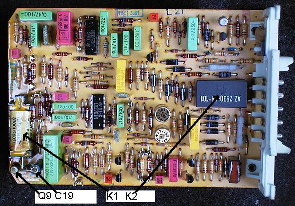
For clarity, here are the locations of Q9, C19, and relays K1 and K2 (actually
reversed from the numbers shown).
On one board, (the one that never
worked) the faulty join was in the output stage before it got to the output
transistor (Q1). The join was simply poorly soldered, and was nicely covered
with all the crap they dipped the board in. For the second amp, the problem was
at the connector where it was soldered to the board.
Part number on Q9 is BSV81 n-channel mos-fet 30v, 0.05a - T0-72 case.
((That part must be ancient. The only reference I can find to it is from NXP
(Phillips) go to page 6 of selector guide
It says it is a depletion mode MOSFET. I am not that familiar with that type of
part and wonder if that is really the part in the cruise control box. I haven't
seen a symbol like the one on the schematic (no arrow). I would assume the four
leads are Drain, Source, Gate and Body. A negative voltage on the gate with
respect to the drain turns it off. Rick))
Tim
__________________
1986 911 Cab
1993 Chevy 3/4 Ton
1997 Club Car
-----
"First off, thanks to James Mahaffey, a MB affectionato, we now have a
description of a similar, although not identical VDO cruise circuit."
So, it's the schematic of the early Mercedes Benz cruise control, as the Porsche
cruise control uses 2 quad comparators, i.e. 8 comparators and figures 1-5 only
indicates 5 comparators. Thus, a questionable and incomplete schematic, right?
__________________
Have Fun
Loren
Systems Consulting
Automotive Electronics
------
Replace ALL of the Electrolytic Capacitors. They dry out from age & fail to hold
the charge.
This will cause speed surges &/or failure to operate the CC at all.
If you are working on any VDO made C.C. (Mercedes, BMW, Porsche, etc) this
applies to all 12-pin, pre 1981 & 14 pin, 1981-1993.
The 14 pin has two 10 mfd axial, two 2.2 mfd axial. one 22 mfd radial & two non
polarized yellow .01 mfd.
If parts are not at the local Radio Shack try
http://www.tubesandmore.com
Search for capacitors on the Home Page left side. Good prices.
----
As far as I could tell there are only 2 electrolytic capacitors (2 x 47 µF 63
V). I replaced those with Panasonic EEUFC1J470B.
However, this did not fix the cruise control (it is still surging).
What should I try next? I have read that replacing the two comparators LM2901N
might fix the problem. What do you think?
I finally succeeded in repairing
the Porsche cruise control, after replacing the two LM2901N quad voltage
comparators; quite happy with it, even though for 12 years I have been
convincing myself I don't really need a cruise control :-) .
Just want to add that I don't want to spoil anybody's business repairing cruise
controls, if you are not used to soldering (unsoldering the 14 pin integrated
circuits is the hardest) it might well be worth paying somebody some money to do
it ... and anyway the person advertising on ebay (mentioned above) would only do
repairs within the US.
I can safely say that I had at least 1 cold solder spot somewhere on the board
(before I resoldered everything the cruise control did not work at all), and
that at least 1 LM2901N was bad. I cannot say for sure that an elco was bad,
because I replaced the elcos first and when I then tried the cruise control it
behaved essentially like it did before, but from other posts it is quite clear
that the elcos very likely go bad with time, so do replace them anyway, it is
easy - much easier than the ICs - and they are cheap.
PS: Just comes to my mind I could test all the components I removed, but that
really wouldn't add any more info, so I am going to throw them away untested :-)
Thomas
------