Hi Francesco,
The power stage switches on as soon as ignition is on. I think that is how it
works in my 1992 GTS.
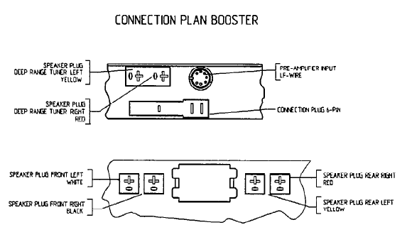
The din cable is used to connect signal from my Becker to the booster, but only
speaker outputs (4x) as far as I remember. The speaker plugs go into the booster
output.
The brown/yellow could be the radio theft alarm. It is not used, intended to
touch ground when the radio is removed and thus trigger alarm signal.
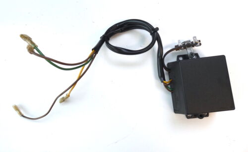
Antenna amp: you connect that to the power-on signal of the radio (if it has
one). This enables the antenna amp when you turn the radio on.
I don’t have a clear picture of the connections, but to power on the booster you
should have a brown wire to serve as gnd, a red wire as 12v permanent, and a
switched on 12v red wire that carries 12v when ignition is on and has the
interference suppressor in line (you can hear a relay click when the booster
switches on I believe).
Speakers are like this:
Brown/Black & Blue - Left Front (runs 2 speakers in driver's door, separating
filter in door)
Brown/White & Blue/White - Right Front (runs 2 speakers in passenger door,
separating filter in door)
Green & Brown - Left Rear (runs mid tone speaker at driver's side back seat and
speaker in hatch)
Violet & Brown/Black - Left Rear (runs 6" speaker in driver's side back seat)
Brown/White & Green/White - Right Rear (runs mid tone speaker at passenger side
back seat and speaker in hatch)
Brown/Violet & Violet/White - Right Rear (runs 6" speaker in passenger side back
seat)
8Pin DIN:
1 N/C
2 Red – Front left
3 Green – Front right
4 Black - Common
5 Yellow – Rear right
6 White – Rear left
7 N/C
8 12V switched by Radio activation
Pin #8 in the DIN connector is switched 12v if your radio
connects a 8pin DIN. It acts as the booster on signal. The diagram above
is from a 1994 GTS, but shows the DIN link and the wiring.
Theo
1992 Porsche 928 GTS
----
The speaker wiring varies per setup. The pre 1989 version has 8 speakers and the latter one has a 10 speaker setup. This also inpolicates the booster connections, as the early one is 4 channels, and the latter one is 6 channels.
The schematics make things clear:
This is the 8-speaker setup, so 4 channels feeding the speakers (L/R front, and L/R rear). Crossover filters split the signal for midrange, woofer and tweeter.

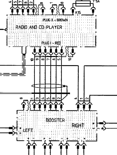
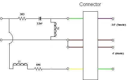
Now, this is the 10 speaker setup:

You may notice 6 channels driving the speakers: 2 fro front (L/R for the front speakers), 2 for the rear woofers (L/R direct link from the booster), and 2 for the tweeter and midrange in the rear (L/R with a crossover filter on the back of the woofer)
-----
pre 1989 crossover filter. Front crossover (left) and Rear crossover (right) (made by Chris Ford, but this was all wrong. The Front seemed ok, but I modified the rear so that it makes sense)
And this is from the 1989 onwards 10 speaker setup. You can see that the in the pictures below that the woofer in the later 928 is connected directly, and the crossover has a separate feed.
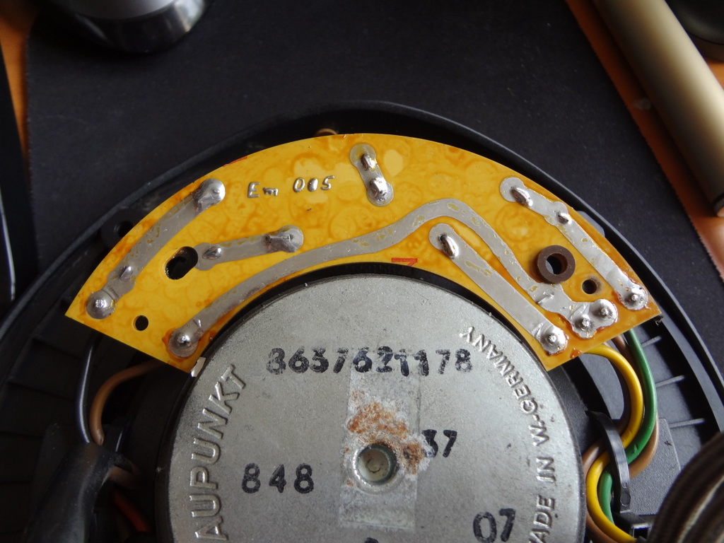
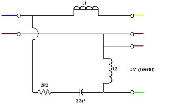
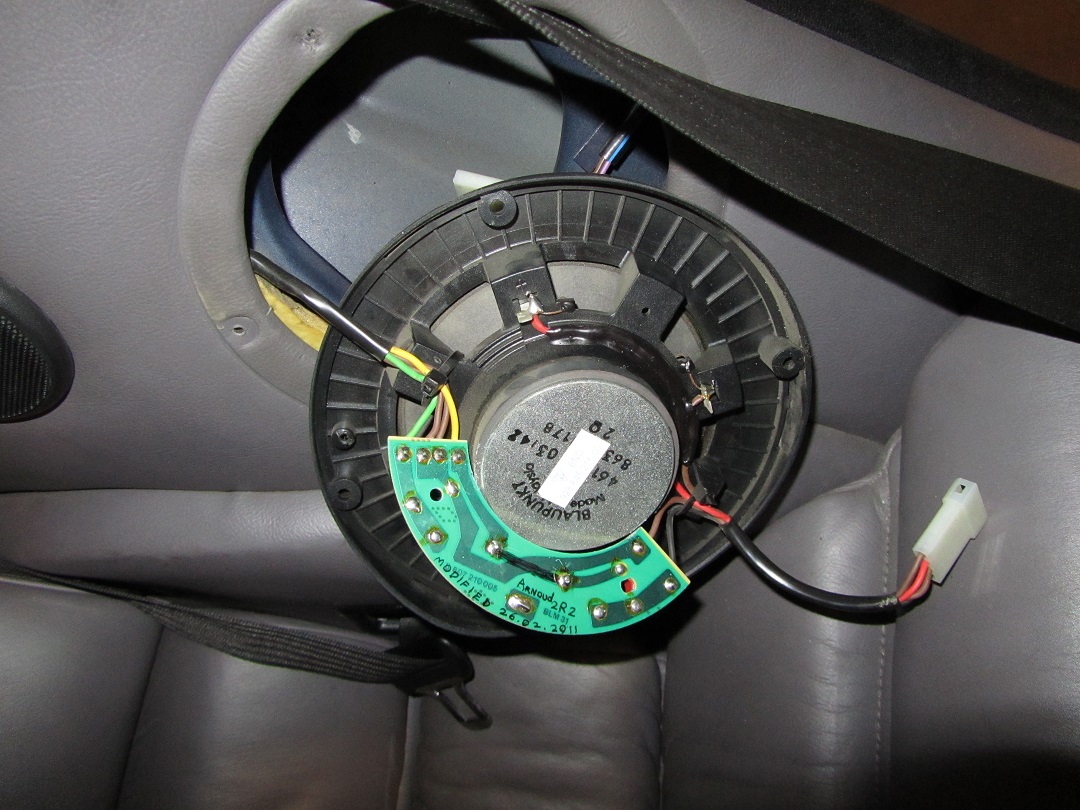
Here is a modified version f the filter:
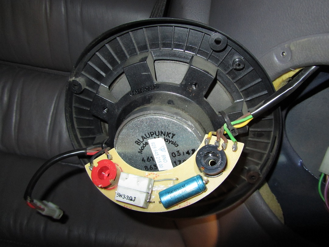
tight space, but the Blaupunkt 8637621178/9 fits nicely.
The capacitor is a 3,3uF bipolar "Tonfrequenz" for a 35volt supply.

This is also what my GTS crossover looks like: the green wire goes to the tweeter. Word is that some models have the connection to the high range tweeter reversed, where the tweeter output is connected to the rear mid-range speaker. That can't be good :) Theo.

Porsche 928 GT door switch crossover loudspeaker 92864544100