Comment by Theo: This is a
remarkable attempt to rebuild a waterpump. Compliments to Bart Jan. But I'm not
sure this is really a good idea unless you have the tools, skills, and a free
running 16v engine.
Overhaul of waterpump DIY
--------------------------------------------------------------------------------
After posting an earlier thread where I asked for experiences with overhauling
the waterpump, I had the feeling that it hasen't been done a lot. Since I'm
selfish, I went down that route to find out it was a hard, but nice one.
Main reason for me to do this is to find out whether I succeed. Second reason is
the current prices of these pumps, while they're getting more difficult to buy
new.
In this post, I'll try to explain what I did. First dismantling the old one and
finding the rootcause of it's failure (It had only done 8000 km from new or so...)
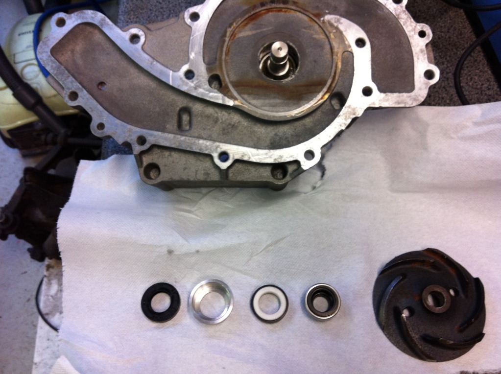
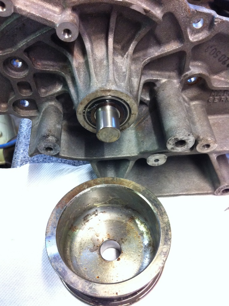
Of course, it all started with dismantling the old one. Luckily I have a 10 tons
press at work that I could use. When assembled, this is what it looked like:
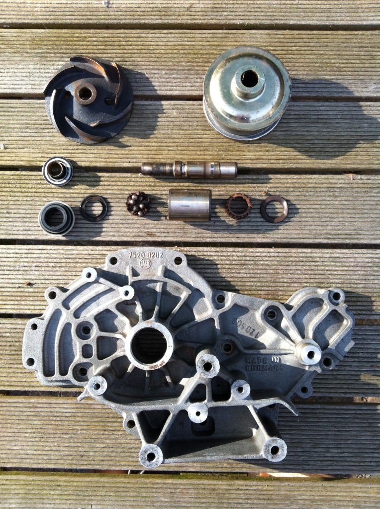
As can be seen, the roller bearing is completely rusted, like many of the rest
of the bearing surfaces. The shaft had a lot of play before dismantling, which
is probably due to a broken water seal. The seal consists of basically two parts:
a ceramic disc and a graphite disc that are pushed on to each other by a spring.
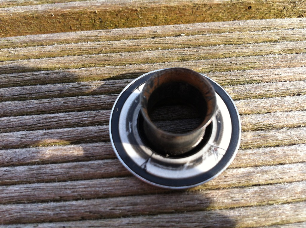
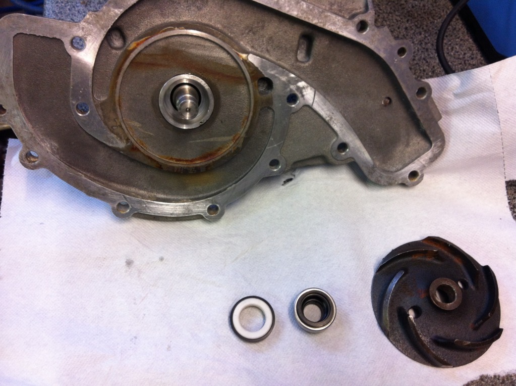
This is the ceramic disc held in a stainless steel container with rubber in
between. It it fixed on the shaft and rests with the back (the side resting on
the table) on the impeller. The disc is quite thin and is broken in many pieces:
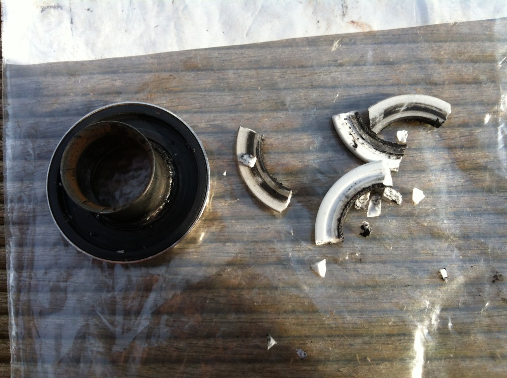
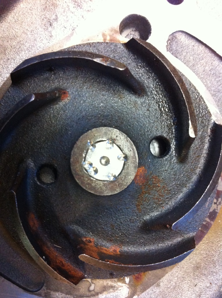
The root cause for the ceramic disc to be broken is probably rust on the
impeller, pushing away the stainless holder under the ceramic disc. This way,
the ceramic disc is not pushed evenly on it's counterpart, the graphite ring
attached to the housing of the pump.
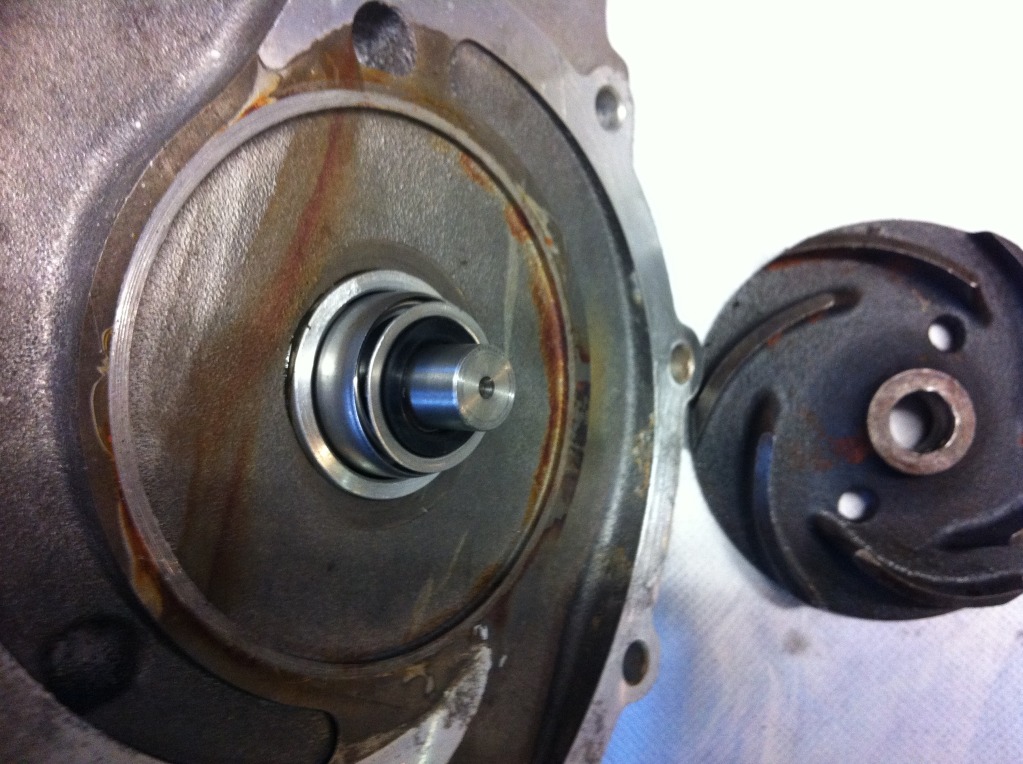
Water can now seep through the water seal, pushing against an oil seal which
rests behind it to keep the oil/fat in the bearing. After some time, this seal
will fail, because it is not made to keep out (hot) water at pressure. When the
cooling water enters the bearings, well than hell breaks loose for those little
balls and shafts inside...
This probably is the reason for pumps with a plastic impeller to have a longer
life than metal ones.
Rebuild started with setting requirements and after that finding suitable parts
that would be able to fit or made to fit.
Basic requirements are:
1. water seal for keeping out coolant
2. axial bearing to keep the shaft in place and to put mechanical force on the
water seal
3. radial seal for those huge timing belt forces
4. oil seals to keep the bearings lubricated
5. water seeping through exit
First the water bearing. I found one with approximately the right diameter and
length for only 8 Euros. It comes from an industrial irrigation pump.
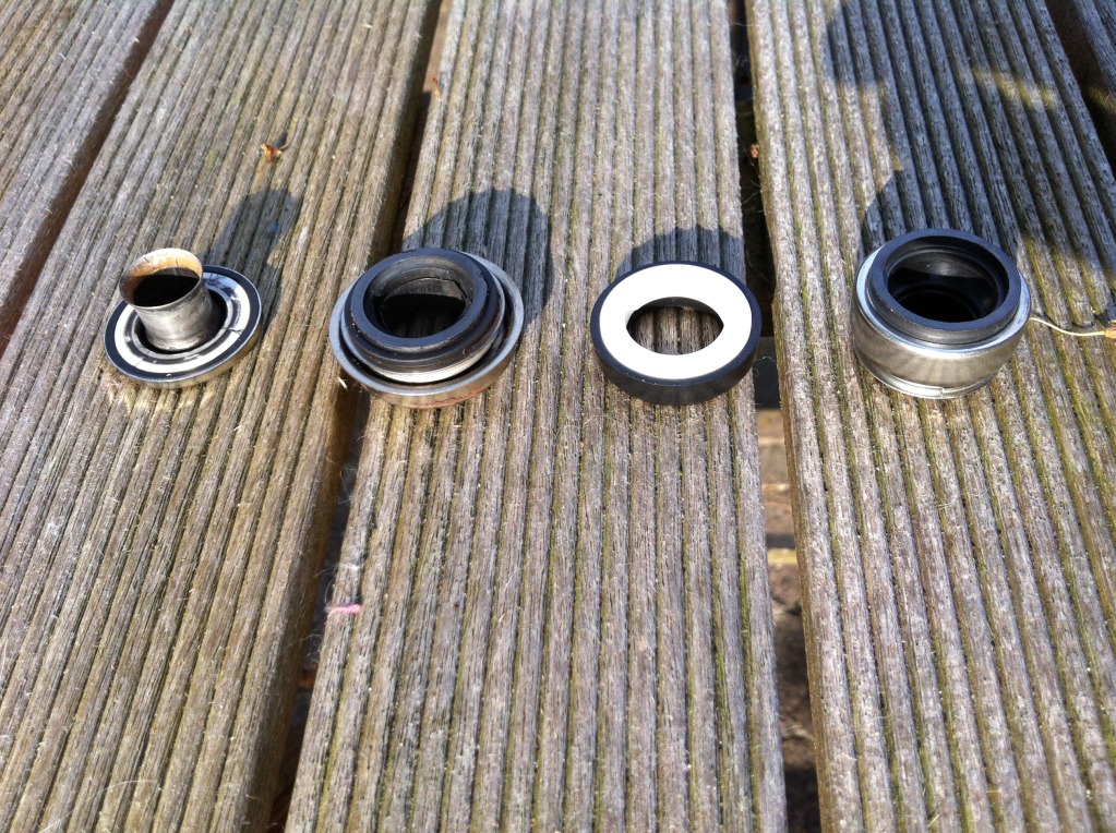
From left to right: old ceramic disc in housing, spring pushed graphite ring,
new ceramic disc (not the thickness!!!), spring pushed graphite disc.
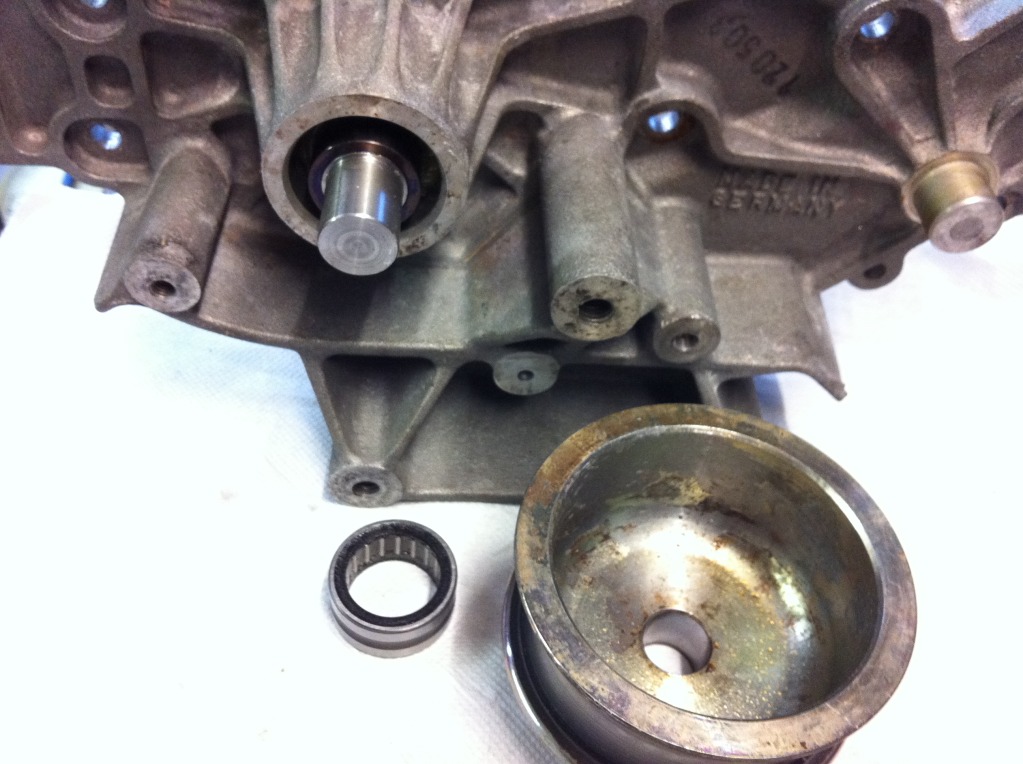
For the bearings I chose to use a single needle shaft bearing with oil seals
integrated and a combined needle shaft, roller bearing:
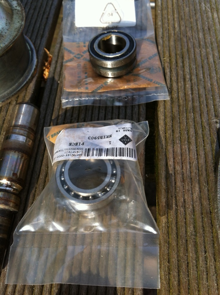
Only one extra oil seal is needed, which can be seen on this image:
Now all was needed is to make it fit. Both bearings and oil seal outer diameters
are exactly 30 mm, like the old bearing housing. So that would fit directly into
the housing. The internal diamete however, is a different story. More about that
in a next post.
Bart Jan
=======
My take on the failure sequence.
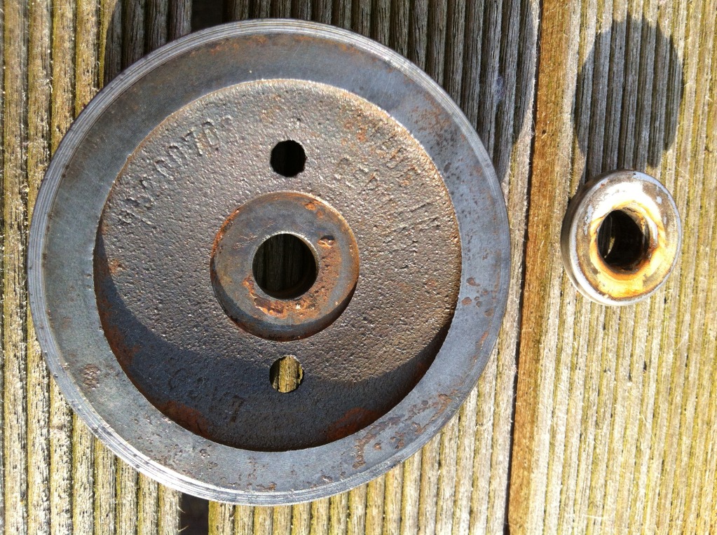
The back of the impeller started to rust behind the stainless base and pushed
the ceramic seal assembly back along the shaft, and broke the seal (sealant at
the interface) between that stainless base and the back of the impeller, and
between it and the shaft, which allowed water to leak along that path. The rust
on the back of the impeller on the seal spot face would support that theory.
Another good reason why a plastic impeller is better than a metal one ... this
failure mode can't occur.
I'm assuming that a sealant is applied (it should be) to the back of the
impeller, and perhaps some on the shaft, to stop water taking that path to
finally travel along the shaft to the bearings. Perhaps on this pump that was
not properly or sufficiently applied.
Water under pressure then travelled along the shaft in sufficient quantity to
defeat the bearing seal, and got to the bearings.
The bearings got sufficient axial play to diminish the pressure of the carbon
seal against the ceramic section and the seal leaked. The ceramic sections of
seals usually fail because of overheating when run without full immersion or no
water at all, which causes them to crack, which would have also contributed to
the volume of leakage. This seal might also have cracked as it was being pressed
apart.
More water got to the bearings ... and it was all over.
__________________
Dave
====
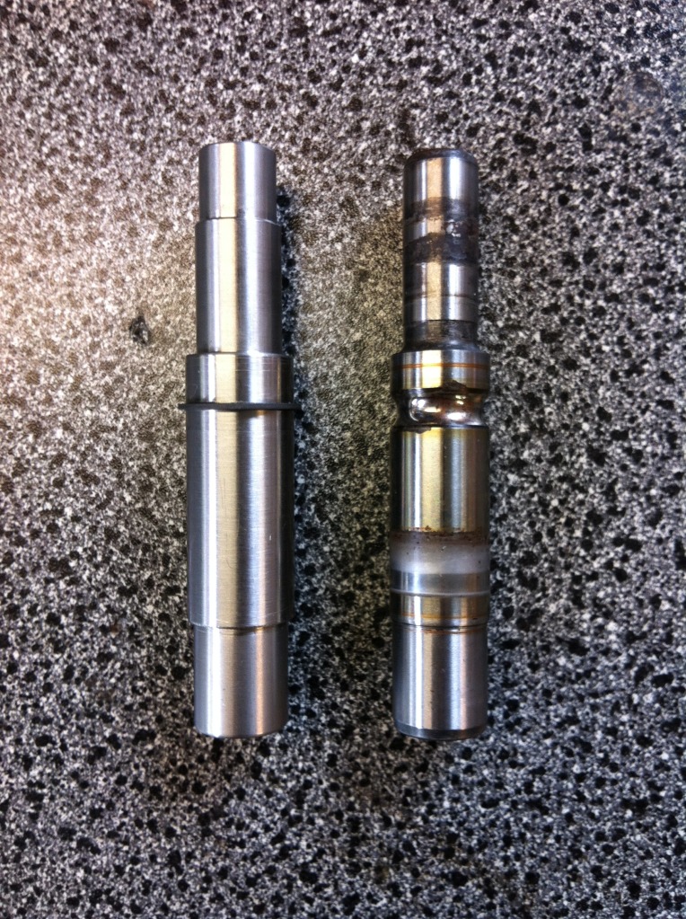
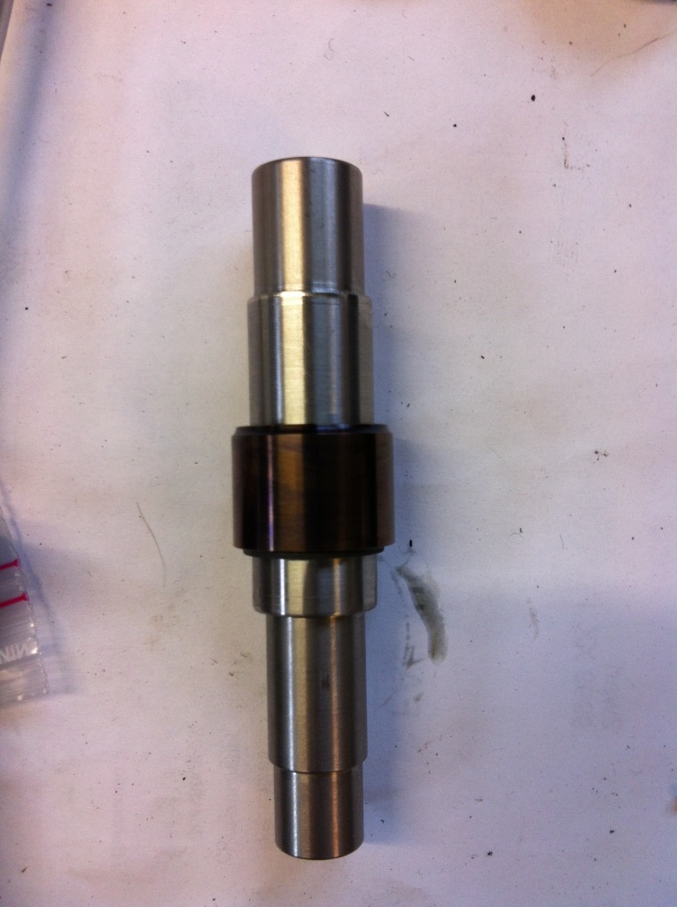
After making the design on paper, I had to make a new shaft to make the parts
fit and seal propperly. This one is made of high grade stainless steel and all
ready has the first part mounted in a groove: a small circlip holding the
bearings in axial direction. On the left obviously the new one; right is the old
one.
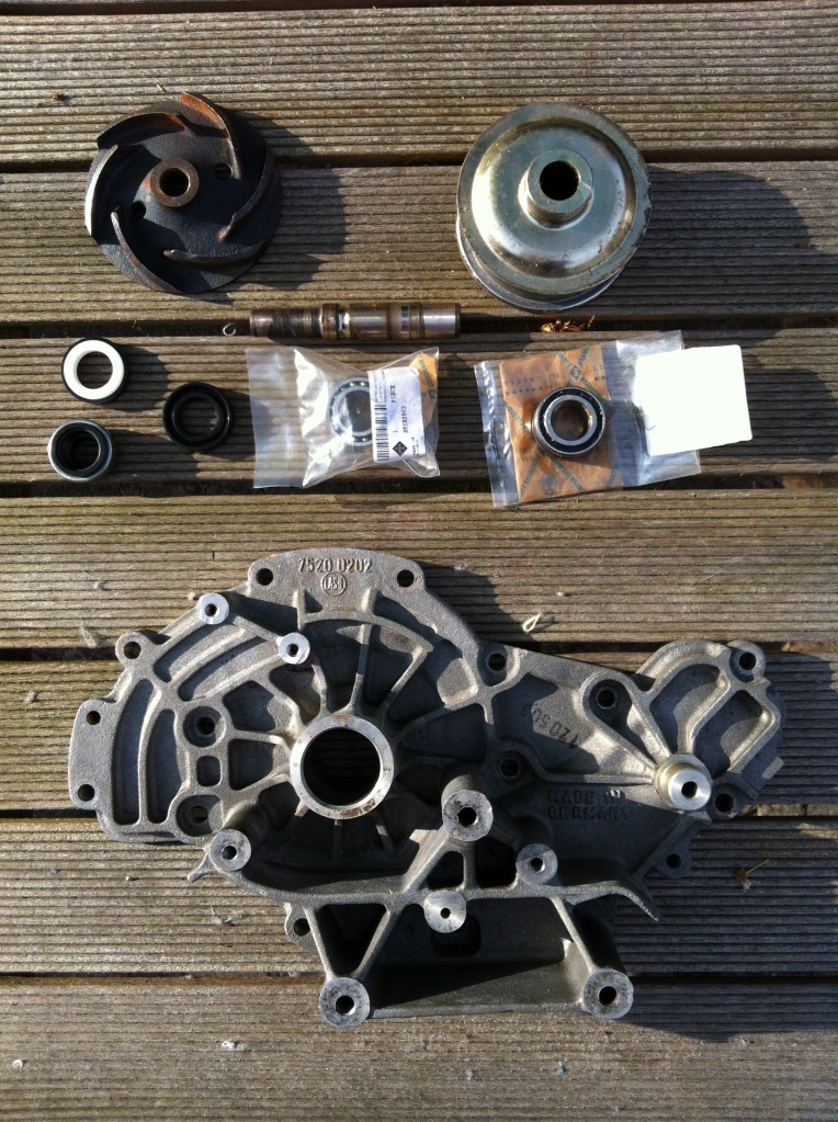
Also, a holder had to be made for
the water seal (rubber + ceramic disc) as it had a different outer diameter
compared to the inner diameter of the pump housing. This part can be seen third
from the right in this image:
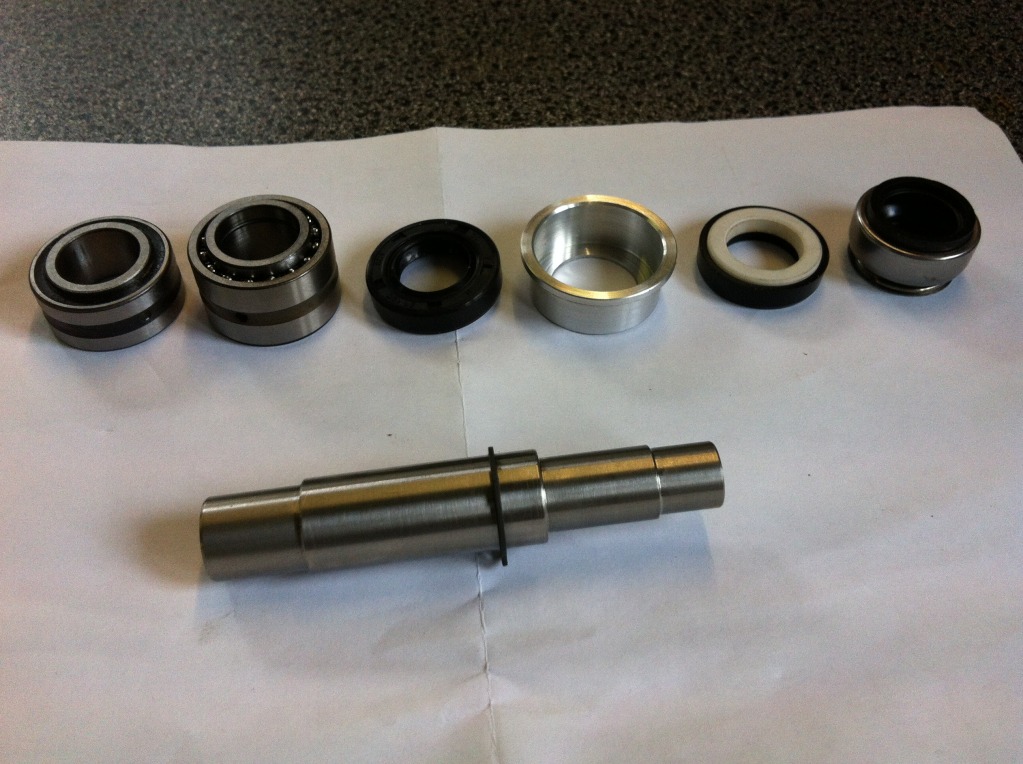
From left to right: single row
needle roller bearing with oil seals, Needle roller/angular contact ball bearing,
oil seal, water seal holder, water seal (rubber + ceramic disc) and finally the
graphite part of the water seal.
The fitting of the parts is very tight, so the shaft was put in the freezer
overnight. The inner race of the bearing heated up in the oven:
The inner race looks overheated,
but that's only the oily bit that was still on.
After that the temperature was stabilised, the single needle roller bearing was
assembled with some high temperature water resistant lubricant. It was put in
the freezer overnight again, before putting the second race on:
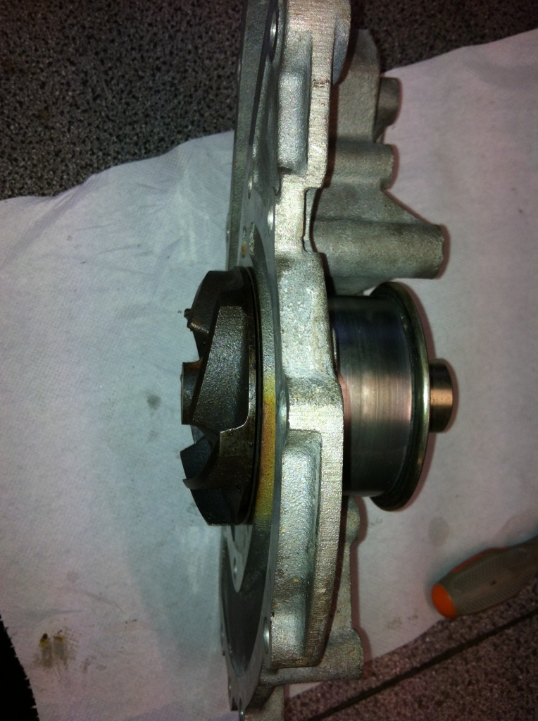
To assemble the shaft assy from the
last photo into the housing, an adapter piece needed to be made on the lathe to
only press the outer race of the bearing and not putting any force onto the
shaft itself. Here you can see it pressing in the assembly:
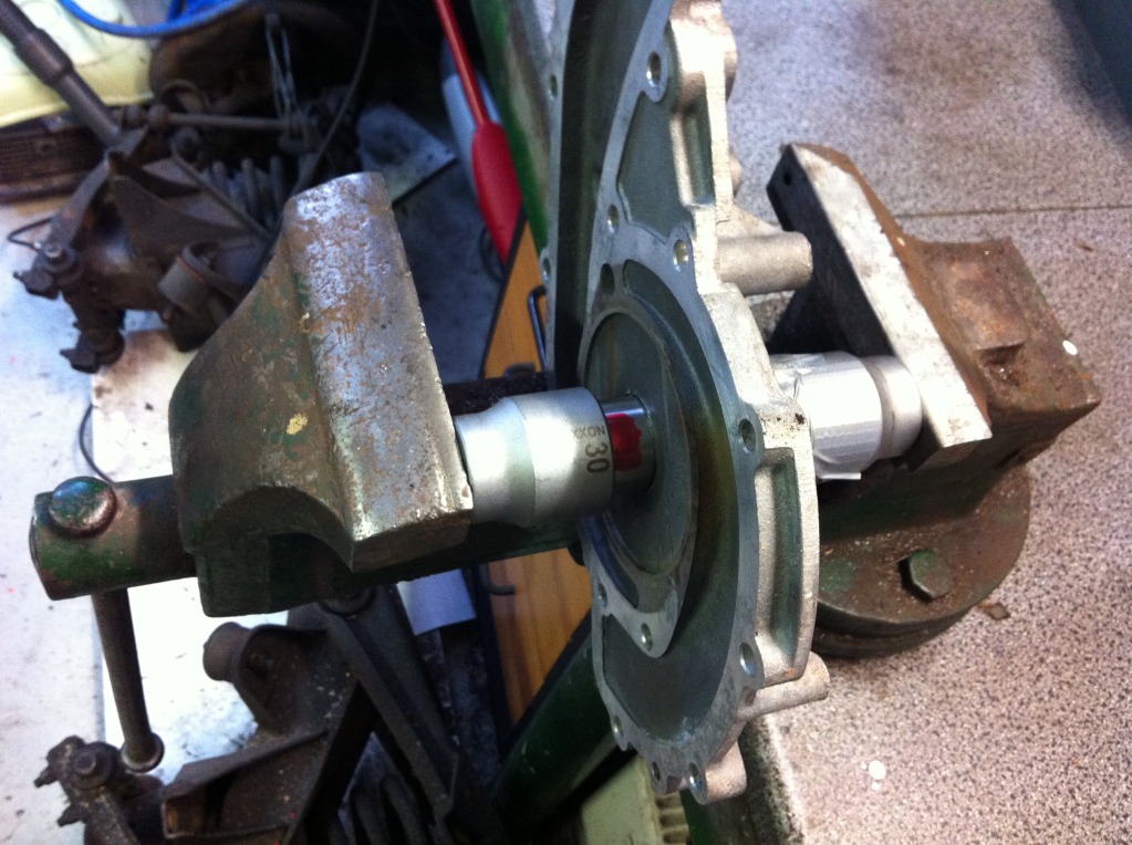
During pressing, I kept a close eye
on the positioning, which I measured with a pair of callipers.
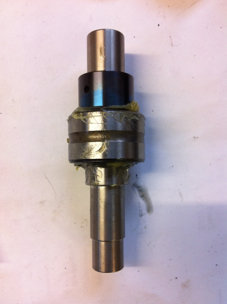
When pressed, it looked like this, with these pieces still to be assembled:
And again a step further:
Here, the water seal is completed:
Then, it was time to go over to the outside of the pump, to assemble the needle
roller bearing with integrated oil seal:
After that, the spinner (or
whatever it's called):
Finally, the impeller went on:
And to be sure it stays on:
Ready!
Bart Jan from the Netherlands
=========
Glad you have a 16V. It is a bit tricky if it turns out wrong.
====
I would have drilled along the shaft axis at the intersection of the shaft and
impeller, tapped the blind hole, and installed (with threadlocker) an Allen
setscrew to ensure that the impeller never moves.
__________________
Wally Plumley
====
The needle bearing has an outer diameter of 30 mm.
There's a huge increase of bearing surface and therefore increase of max.
allowed load on them.
Now, I wonder why you asked;-)
Bart Jan
====