Now, this doesn't matter, 'cause I don't HAVE to disassemble the old setup. Can someone tell me:
1) Obviously I need to shim the new PP before trying to install the new release bearing.....
2) Do I need to insert the release bearing through the new release arm BEFORE laying it on the floor and stomping the PP into place?
3) Once the PP fingers are in the channel in the release bearing, do I need to keep weight on the PP in order to get the C-clip in?
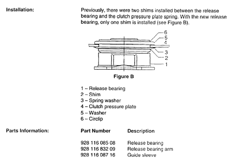
Here's a diagram from a 1994 TSB on assembly of the release bearing, so at least I ought to have the shims and washers in the right place.....
4) Should I just suck it up and take this all to a shop and let them assemble? Sorry for the dumb questions, there are a million posts on this, many with pics, but I can't grok the order of operations here.
===========
So here’s my release bearing/PP assembly pics for posterity, I know this is trivial for most but it was intimidating for me (until I actually tried it, it’s a piece of cake. Duh.)
So- first one must shim the PP in order to release some of the pressure on the clutch fingers:
Compressed, ready to accept a shim:
PP shims, made from aluminum L-channel:
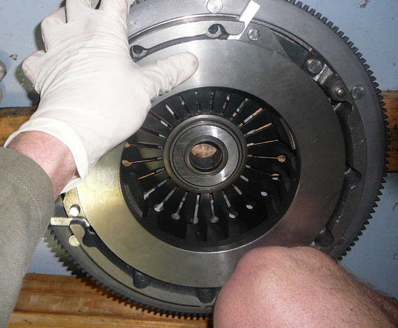
And here are the parts that come with the release bearing, numbered in order that they're assembled:
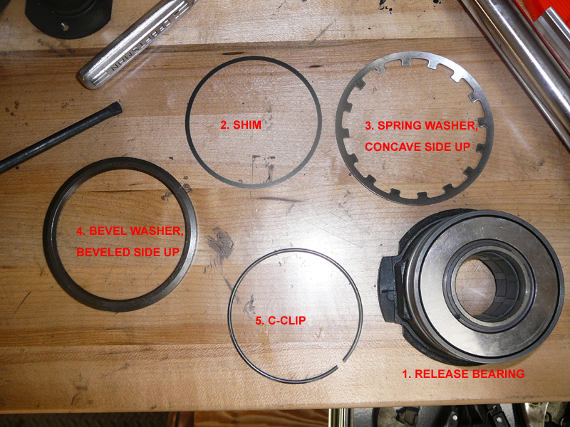
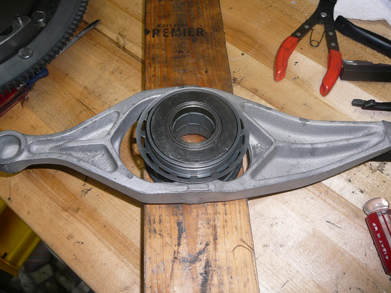
Start the sandwich by putting the release arm engine side up across a 2x4. Then center the release bearing, and add the shim and the toothed spring washer, concave side up. They sit on a shoulder on the release bearing:
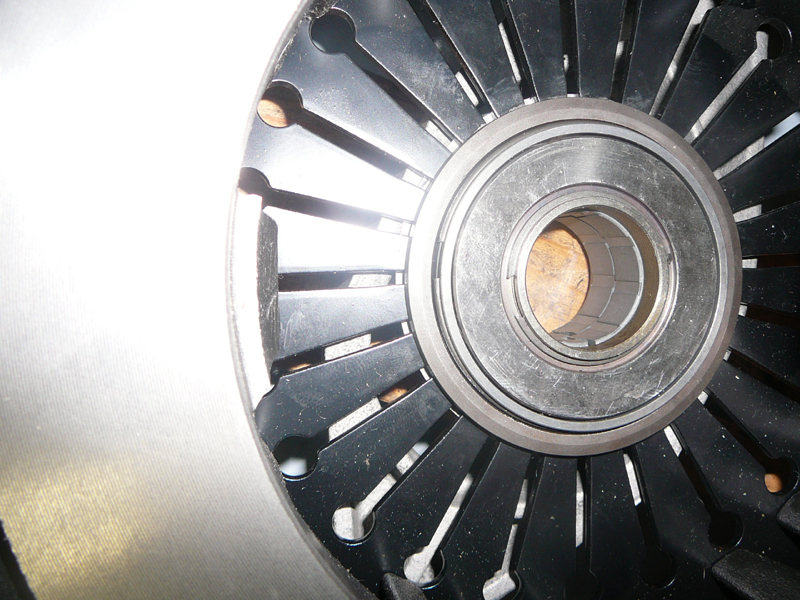
Then put the pressure plate over the release bearing, and then the big thick washer, beveled surface up. The c-clip is going here:
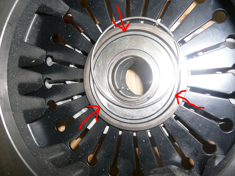
At this point, you will find that pushing down with both hands on the PP assembly will flex the fingers, exposing the groove in the release bearing where the C-clip sits. This requires about 40-50 lbs of force. So the trick is to put the whole thing on the ground, kneel on the PP so that the fingers flex, then just maneuver the C-clip into place with your free hand. This does NOT require snapring pliers! I just started the mid portion of the C-clip into the groove, then pressed it in along one side, then used a small screwdriver as a pusher stick to seat in the other half around and into the groove on the relase bearing :
Once in place, remove your knee from the assembly and the c-clip is almost drawn into place:
The assembly’s ready to go back in the car. Now I just need kids to go to sleep so that can happen!
_____
Rob Edwards
=====================
To follow up on assembling the PP/ release bearing, having survived the process, I have a few pointers for clutch re-installation. This is actually straightforward, but there are a few obvious things that aren’t obvious until you actually do it.
Nota Bene- This seems to have worked on my ’90, I may have done something wrong, but it hasn’t grenaded yet. Dunno whether there are any specific gotchas for other S4 model years. YMMV.
For the real mechanics here, if anything I wrote is incorrect, PLEASE chime in!
Pointers:
1. Once the PP/arm/release bearing is all together, get under the car and look at the flywheel, note where the locator pins are, 1 big one and 2 small ones. I rotated the engine by hand so that the big pin was straight down at 6 o’clock. I then made a mark with a marker on the edge of the PP in line with the big pin so I could lift the assembly into the bellhousing with the mark at 6 o’clock.
2. I did not need to drive any locator pins in or out of the PP during either disassembly or reassembly. This may not be the case for other years, or I’m just a moron and got lucky.
3. Leave the shims in the assembled PP/clutch assembly. When you start tightening the PP-to-flywheel bolts (step 15), the shims will fall out one by one.
4. Install the nylon release arm cup onto the ball on the bellhousing. I sprayed a small amount of lithium grease in there, and it still took a surprising amount of force with a prybar to get it to seat on the ball.
5. Assemble the PP, guide tube, intermediate shaft, and friction plate. I tracked down some Optimoly HT (now called Montagepaste, P/N 000 043 004 00 at the local Porsche dealer). It is like LM508 Copper antiseize but is much stickier. There are five things to lubricate:
1. Intermediate shaft sliding surfaces where the clutch disc sits.
2. Ball cup bushing on arm - lithium grease
3. Contact point between throwout bearing and arm- Montagepaste
4. Rear splined end of the intermediate shaft - the part that slides into the clamp sleeve to the torque tube- Montagepaste.
5. A little dab on the end of slave clutch cylinder piston. Basically any parts with metal to metal contact that a) need to come apart again or b) slide, slip or pivot. (Thanks to Dave C for this list!)
6. According to a TSB I found the GTS guide tube gets no grease of any kind (bolded at the bottom), there are several posts that mention this but I'd not seen the TSB posted:

7. Slide the torque tube coupler onto the torque tube shaft back into the torque tube to get it out of the way. Slide the guide tube all the way forward into the release bearing. To get the clutch pack up into the bellhousing, the rear of the intermediate shaft has to be positioned within the release bearing so that it is JUST forward of the flanges to which the guide tube mounts.
8. I had the car up on 6 ton jackstands, so the bottom of the bellhousing was about 18-20” off the ground. I tried to use a jack on which to rest the clutch assembly, but then the jack was in the way. SO- With a pair of 3 ton stands and a 3 foot length of 2x3, I built a 15” high ‘crossmember’ that sat just under the bellhousing, so that I could rest the clutch pack on it when it was part way up into the housing.
Check out this high tech drawing:

9. Have one of the PP bolts nearby. Flat on your back, piece of plywood on your chest for protection, pick up the clutch pack, make sure the mark is at 6 o’clock, and that the relase arm is pointing straight up. Heft the assembly into the bellhousing. It needs to be STRAIGHT up and down so that the friction plate slides up and in in front, and the intermediate shaft fits in back. Move the 2x3 into position on the 3 ton stands and you can rest the assembly there. Rest your arms.
10. Lift the assembly up into the bellhousing, the goal is to A) get the big locator pin on the PP into the hole in the flywheel, and B) get the intermediate shaft into the pilot bearing. I think I only got part A done, and then I put in one of the nine PP bolts. They’re long enough to engage 2-3 turns of thread.
11. You can reach through the ‘windows’ in the PP to to jiggle the friction plate around to get it so you can insert the intermediate shaft into the pilot bearing. Once it is in, you’re golden.
12. With the PP shimmed, you ought to be able to rotate the rear end of the intermediate shaft and watch the friction disc turn.
13. Rotate the motor and install the remaining PP bolts in crisscross fashion. I put them all in finger tight but didn't torque them down yet.
14. At this stage, the PP is still shimmed, and the release arm can be slid around relative to the release bearing. From below, maneuver the relase arm so that it is sitting partially on/over the ball cup bushing. Once everything is re-assembled (including the bellhousing cover, clutch slave and pushrod), the arm is seated on the nylon bushing by pushing the clutch pedal to the floor.
15. Start torquing the PP bolts down in crisscross pattern, turning the motor by hand. The shims fall out during this step.
16. Pull back the guide tube and bolt it to the flanges in the bellhousing. These were a little hard to start but once the first was in, the second was easier ('cause the intermediate shaft was then aligned?) The final product looks like this:
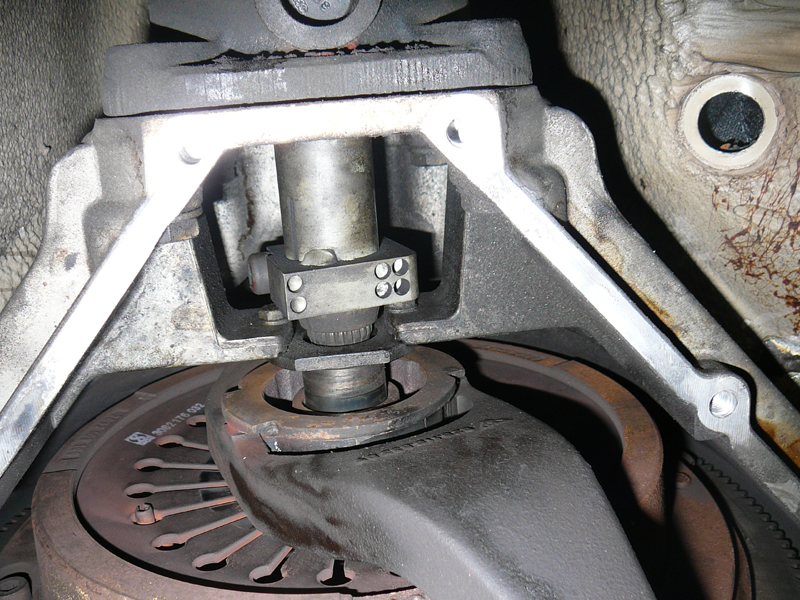
17. Move the coupler into place and rotate the motor so that you can see up the bolt holes in the coupler. The intermediate shaft needs to be positioned in the forward-aft axis so that both coupler bolts will line up with the grooves in the intermediate shaft (forward) and the TT driveshaft (rearwards) Then the bolts can be installed and torqued down.
18. Button up bellhousing, reinstall starter, clutch slave, pushrod, etc. I left the rear pair of bellhousing bolts out for future misadventures without having to drop the exahust. I didn't need to bleed the clutch.
__________________
Rob Edwards
1990 928GT #278, Black