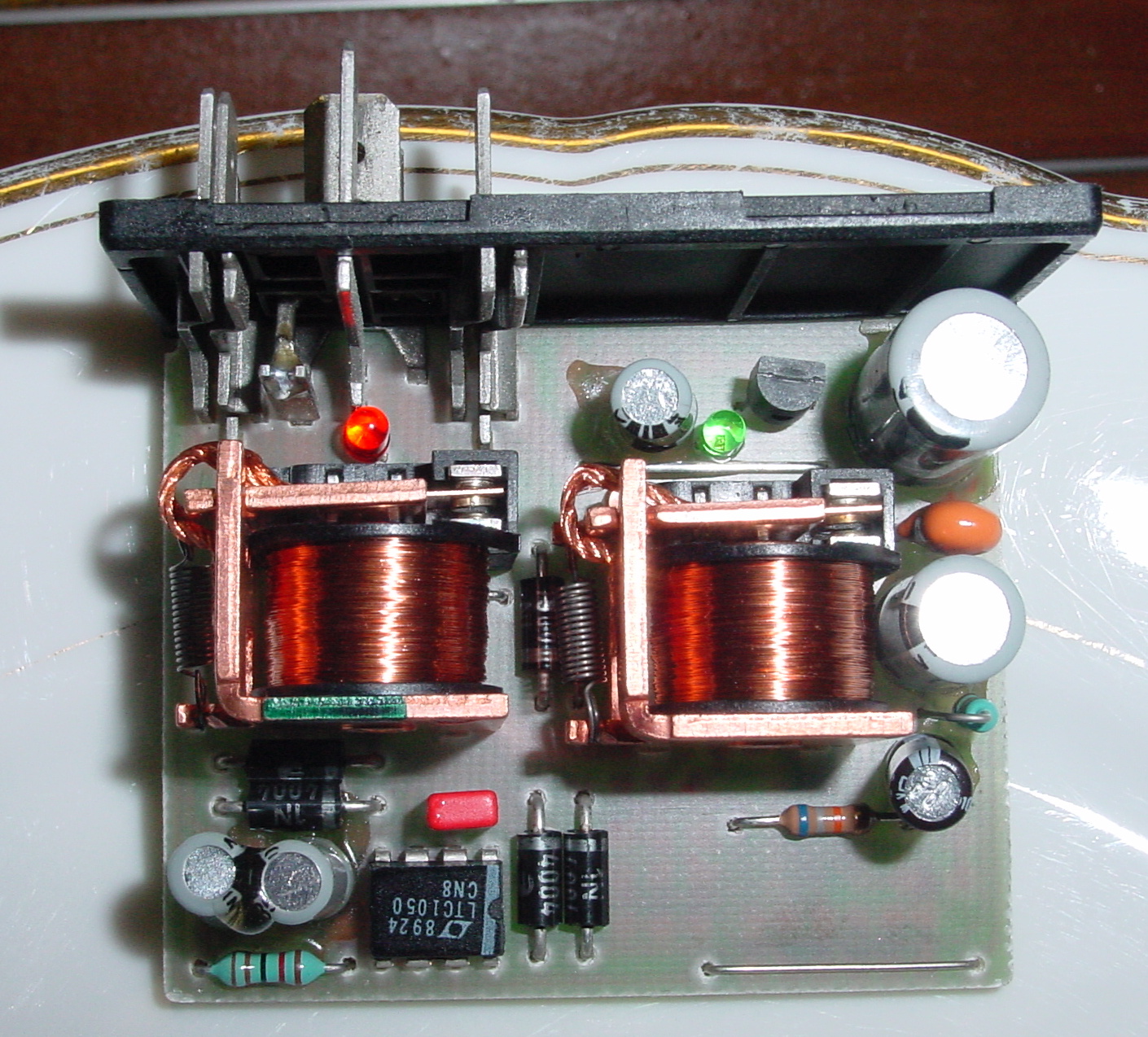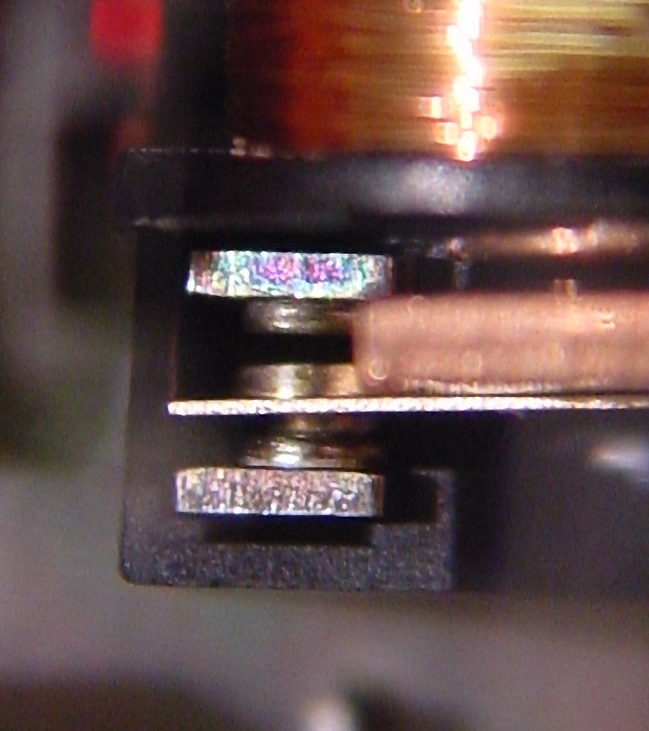
This shows the internals of the IMR, the Ignition Monitoring Relay. The operation is pretty basic as you can see. It utilizes a LTC1050, a Precision Zero-Drift Operational Amplifier with Internal Capacitors. A common failure is contact resistance of the Relay contacts. The contacts carry the load for Injector current for a batch of 4 Injectors, so substantial current is flows at times.


In normal operation, the relay is not engaged and the contacts from the main Power (supplied to pin 87 by the LH relay) flows via the relay to terminals A1 and A2 which each feed 12v power to a group of 4 injectors. When the IMR sees a difference in output from the temp sensors (voltage between E1 and E2 terminals as much as +2.5mV or -2.5mV) it decided to activate a relay, causing the power to be cut for a group of 4 injectors, and a LED signals that the relay is now in fault mode.
An engine running with 4 injectors not working makes the engine run horrible, and is a potential danger for the drive shaft in the TT. It is known to break due to intense vibrations caused but an activated IMR.
regards Theo
1992 928GTS midnight blue
The Netherlands