Transmission
switch PRND32
87 S4 auto.
Is this transmission switch on the side of the tranny "serviceable"?
It basically controls the PRND32 and reverse lights....all of which have never
worked on my car in ..oh..7yrs...since i bought it.
Is there a way to trouble shoot it via the pins? I haven’t seen anything in the
manuals.
How much is this bad boy to replace $$$ for those that know.
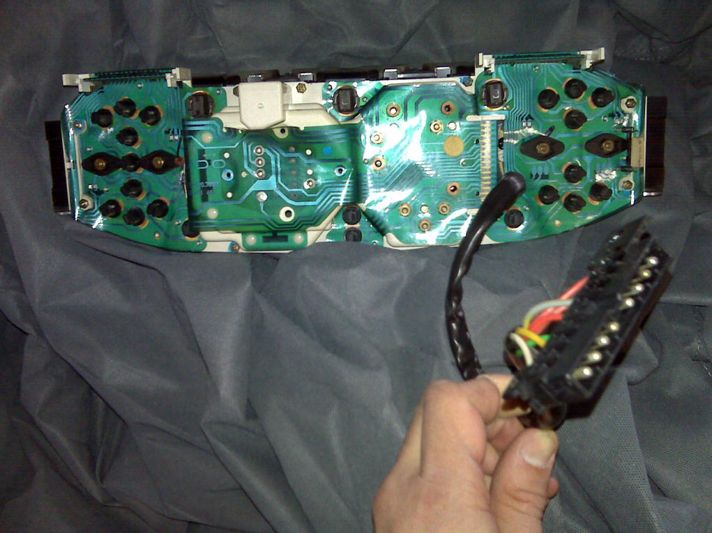
![]()
Tony Harkin
There is a 6 pin
connector in the spare tire well. Check red/black wire
for power. This wire supplies power for shift indicator and back up lamp
function of switch.
Zeus+
i have done this
already and unfortunately i had to take the scenic route. my 85 euro has a
little crème colored micro switch that is mounted on the ignition cylinder
shaft this is were the power comes from the switch to
the lights on the dash . it is a 911 part . good news is you do not have to
drop the cluster . but the switch is what sends power to the switch and in turn
the lights. i did all you have done including a very nice new trans mounted
switch sitting in a box now. look at the micro switch by the ignition switch. This is what sends the power to the transmission
switch. it is a small plastic part that does wear out hooked so when the key is
turned to the on position a lever pushes out and hits the micro switch. this is
what sends the volts out to the trans switch .i will try to find receipt with
part number.
TomShark
fuse #24
controls the rear hatch trigger and interior lights which include PRND32.
__________________
Malcolm
well, that's
the one I have. Just installed it and they still don't work fuse 24 checks good
also
Looks like I'm
to the pod and Keiths idea of lighting the bulbs directly from the connector
leading in?
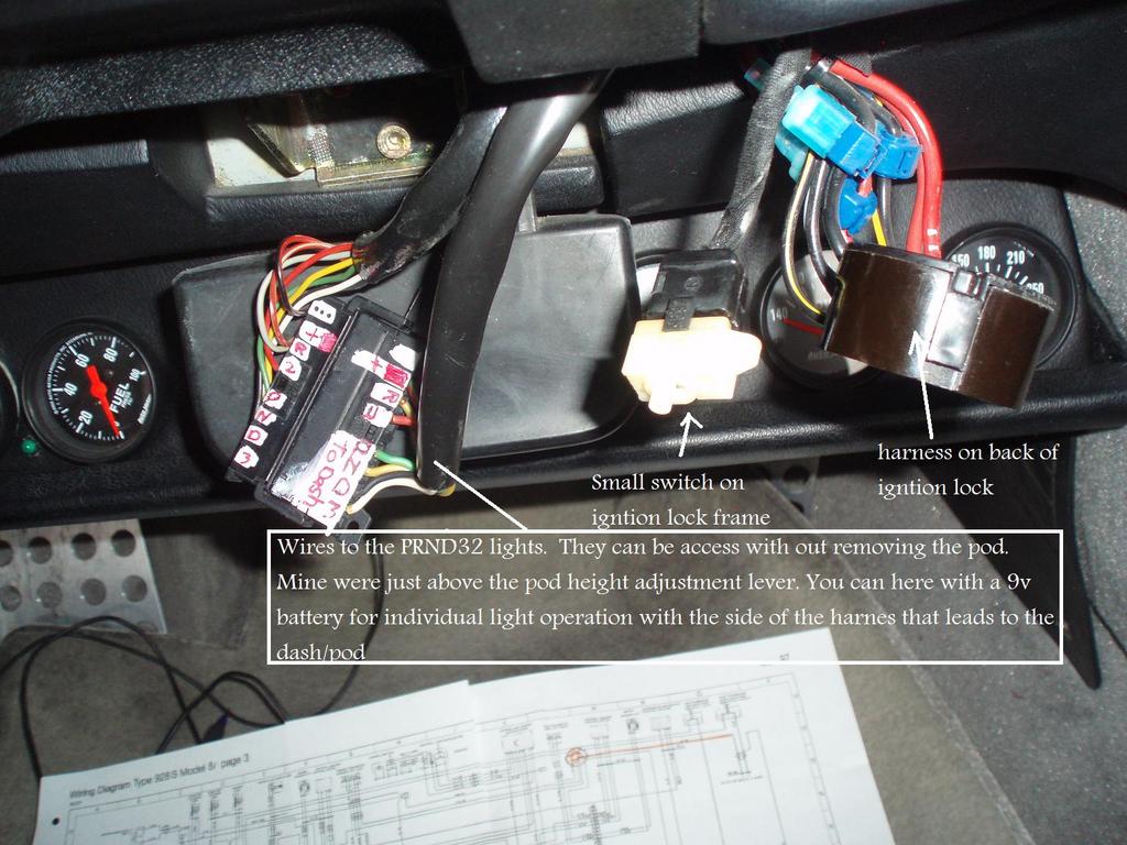
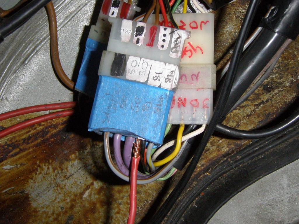
Where does
the harness that has these wires (below) drop out of the pod?
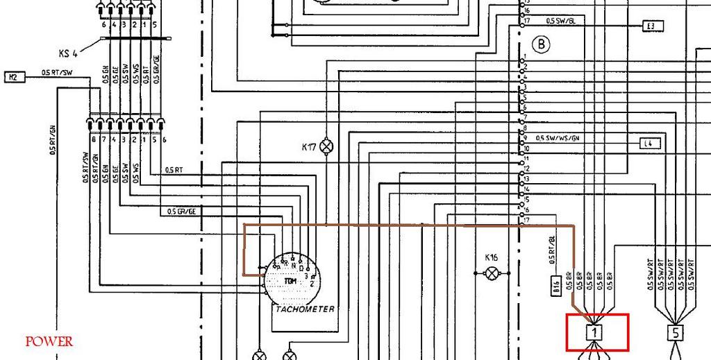
What is the RED
SQUARE?
the key says a "welding point"???
I ask as the wire that leads there from the tach
display i believe is a ground and it grounds the entire display. I have found
the harness that leads into the pod. It was actually easy to get to...right
next to the pod height adjustment.
I reached in and pulled the wiring connector
down...
__________________
Tony1987 S4 Auto
The first step in
checking this circuit is always to clean and check the connector in the spare
tire well...
Find the six-terminal connector in the forward corner of the spare tire well.
Locate the red/black wire in Terminal 5, and check for 12 vdc.
The welded point
is just a place where a bunch of brown wires come together - sometimes hidden
inside the harness, sometimes visible. They all run to one grounding point -
locate MP - IV and check it.
_________________
Wally Plumley
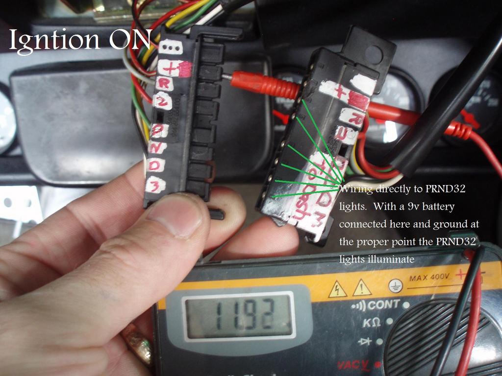
Well, rigged
up a 9v battery to the lights. I ran the ground from the "MP IV"
ground point (above the brake pedal area) and connected each individual wire in
the connecter. I got all the lights except "D" so i assume that one
is burned out. So my bulbs work and the ground must good to them as they
illuminated using their normal ground "source".
So far
continuity is good from the connectors in the trunk to the connection in the
pod.
I get 12v up
to the connector in the pod...so there must be something that controls the
power from that point until it hits the bulbs.....back to the schematics more
to come I'm sure. I may have found a lead (pun intended) Thank you. Too late now to go out and look
though.
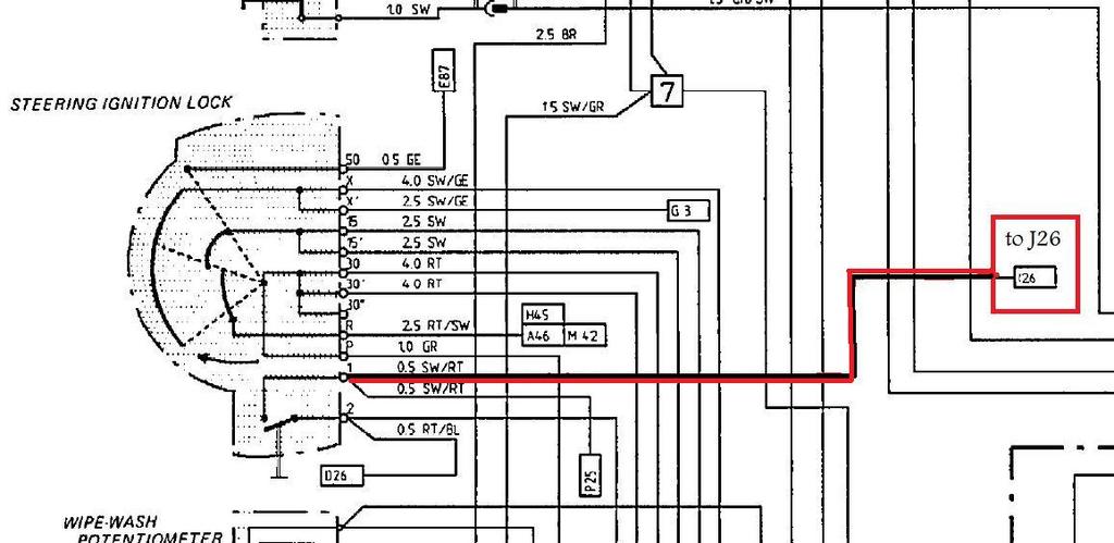
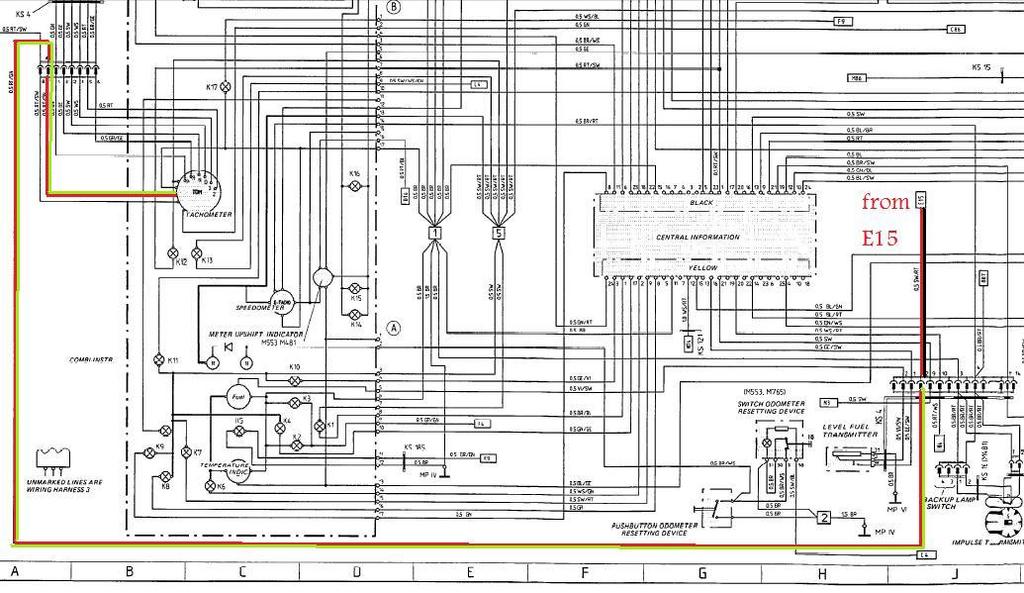
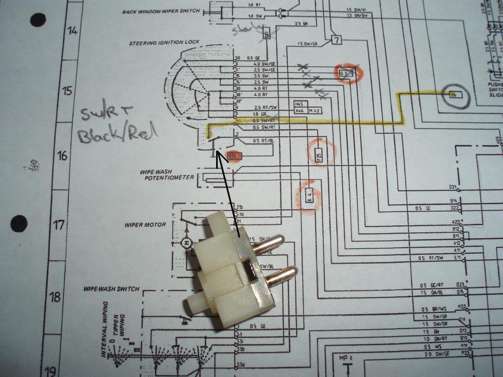
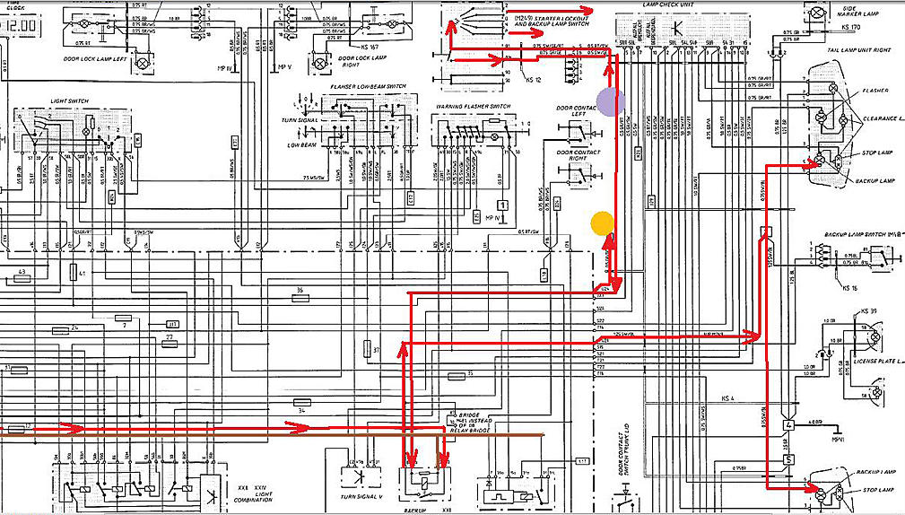
Seems the
ignition switch area does have a link to the PRND32 lights. Power comes off PIN
1 on the switch (grid B16) via a black/red wire which travels to grid J26(on to
another diagram) where the wiring continues to connector shown in grid
B24....then into the tach.
(if you
haven't referenced the diagrams...B16..etc etc are coordinates on the diagram
used to locate items )
Simple
terms...I'm looking for a black/red wire from PIN1 on the ignition that
eventually travels all the way to a connector in the trunk where it changes to
a red/green wire and returns to the pod connector where it then travels to the
tach.
__________________
Tony1987 S4 Auto
it is mounted
within the tumblers reach left of the actual ignition switch. It is mounted to
the steel or aluminum brace behind the dash pod that
holds the ignition cylinder. i remember it is a 911 part.
i just jumper wired around the switch and the dash light park light came on.
this was a mess as i followed all the suggestions others had and that was a lot of work . and upsetting seeing how cheap and easy it
was to fix.
Tomshark
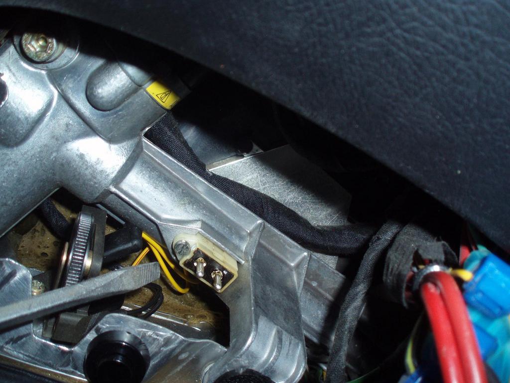
hmm...found
it, a small 1"x 1/4" in white switch held in by a single screw. I
removed it and checked it and it appears to work fine. It is the first switch
that moves when you turn the key a small fraction. It turns on my
"chime". I pulled the switch and jumpered the connection and i get
the chime....no lights though.
pics to
follow of it
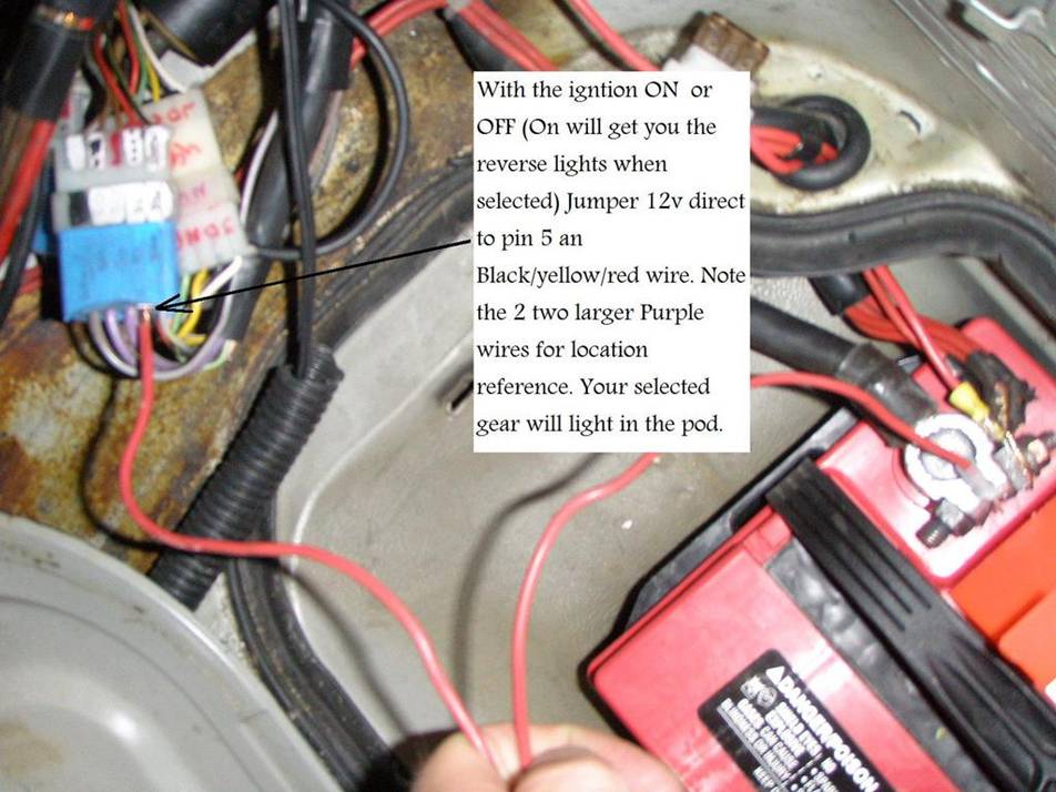
oh..and if
you jumper the tranny switch in the back, pins 1 and 2 of the 3 terminal
connector, your cooling fans go on high! Im learning all kinds of stuff!
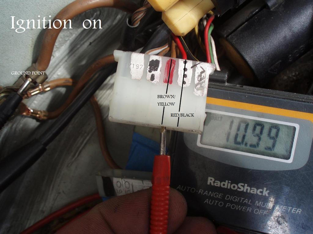
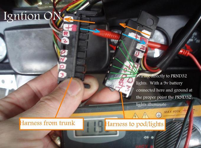
No power
there with the key ON or OFF....as seen below. The voltmeter is grounded at the
factory point in the wheel well. The reading is shown is Mv.
but..i do get
power on the Brown/yellow wire next to it with the key ON. next picture...same
ground.
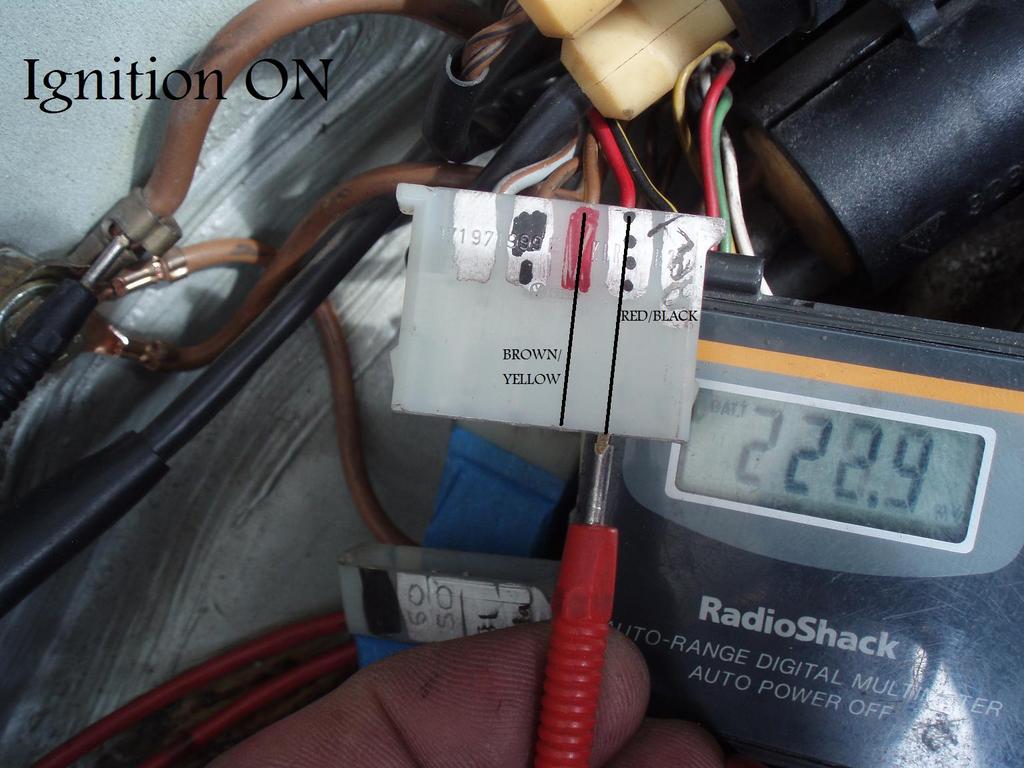
This pic
shows the ignition ON and a good power supply right up to the connector that
takes the wiring up into the pod.
Bottom line
in this i think is i get power all the way to the POD. The lights illuminate
when hooked directly to 9v on the harnes shown below ("to dash"..on
the right) some where between this connection and the bulbs there is an
interruption to the 12v supply to the lights.
anyway...digest it, while I get a match!
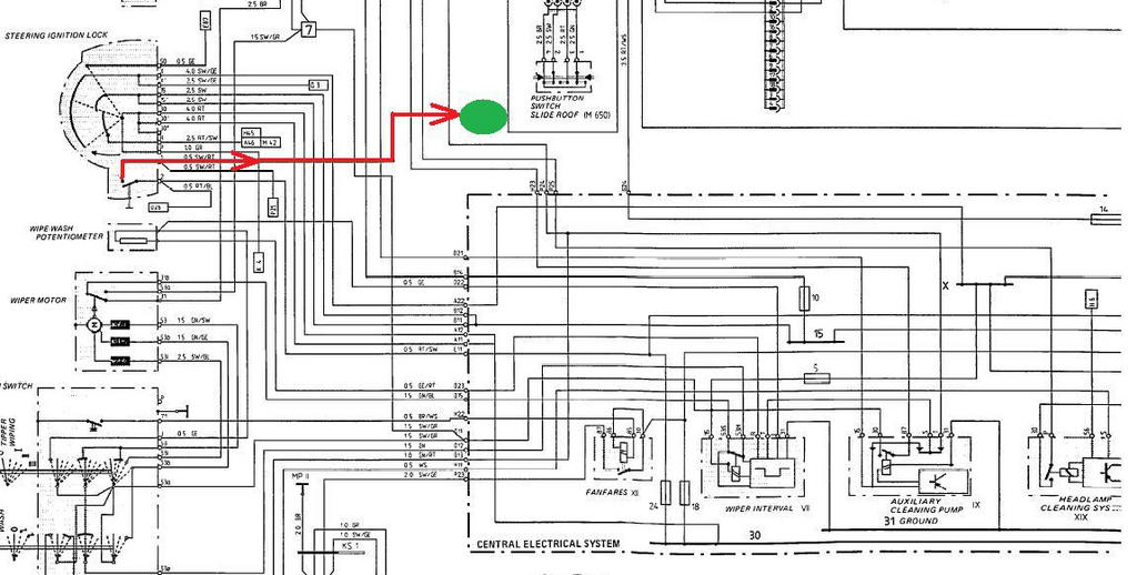
I spent some
time tracing...literally with colored markers the diagrams tonight and came up
with a little test that is easy to do.
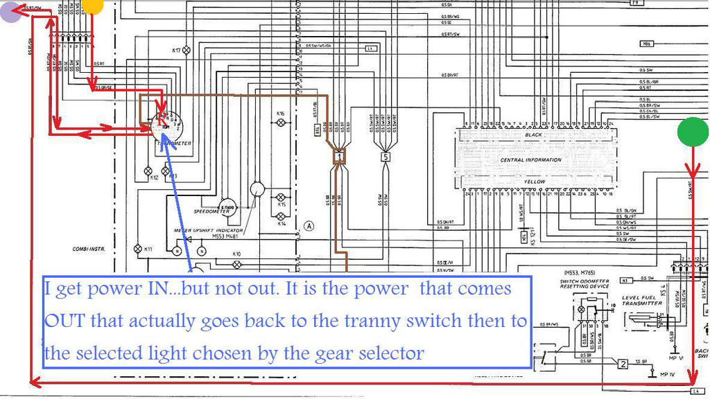
My issue now
is...i have 12 volts going INTO the tach/PRND32 area (pin 7) but I don't have 12
volts coming out. (pin 8)
Look at the
schematic...it may be easier. I lose power somewhere in the pod where the power
comes back out. It is the routing/flow of the power that was tripping me up.
Power actually goes IN (7)...and OUT(8) on the same harness/connector in the
pod. My problem is...it doesn't come out
WHY??
The pod has
to come out anyway to replace my burned out "D" light so may be i
will fined something then?

I'll post this
picture again now that I know that the voltage flows both ways across this
connector..
Voltage is suppose to flow in the direction of the
arrows I've shown. However in my case I don't get the volts across the "orange"
arrow..."out from the dash"
__________________
Tony1987 S4 Auto
Good news: After hours and hours of research and
pouring over wiring diagrams, I was able to fix my PRND32 lights! And what I
found may be a common problem for many of us that have lived without lights for
years.
Firstly, let me thank Tony for his great writeup
(^^^) and where he left off is where I started.
Tony noted that power comes into the PRND32 light connector on pin 7. This
power comes from U25 on the CE panel which is supplied by the ignition switch
in position one. Since the PRND32 lights are also powered by the parking light
switch, power from there comes into the instrument pod into the back of the Tach, hence the need for a relay on the Tach
circuit board to control power to pin 8, which sends 12v back to the switch on
the transmission. This power lead (pin 8) puts 12v on both the backup switch
and the PRND32 switch so when the contacts are closed by moving the gear
selector, that power comes back through the wiring, through the connector in
the spare wheel well back to the lights in the Tach.
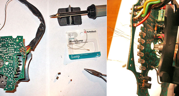
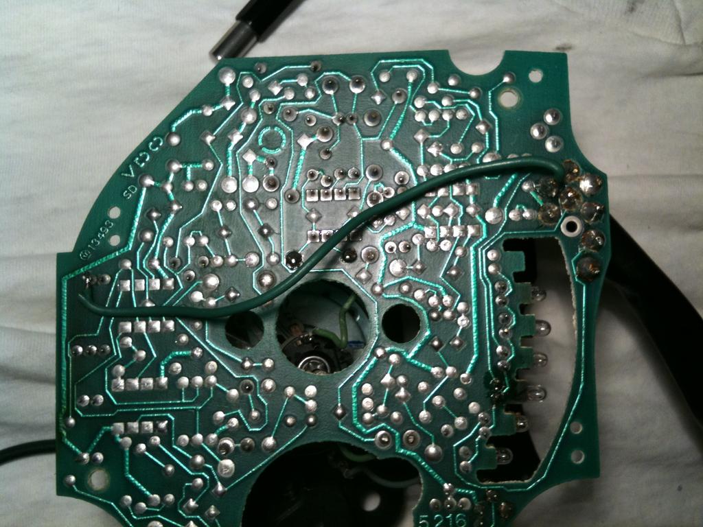
To make a long story shorter, i found a broken trace on the Tach
circuit board. That trace comes from the relay back out to pin 8. That break
was why pin 8 never had any power.
So I jumpered that broken trace as shown below:
I left the picture
in high res so you can see where I placed the jumper. You can easily tell if
you need this jumper by testing for continuity across these two posts. If you
don't have continuity, your trace is broken.
Looking at this trace on the other side of the circuit board, it looks really
thin where mine broke and could be symptomatic of all 928's and quite possibly
it acts like a fuse and opens the circuit.
Hopefully this will help others with this problem.
__________________
Bob Ungaretti
Nicely done "Dr Watson'!!
Thank you for taking the investigation
deeper into the pod and more so sharing it here. I wasn’t about to tear that
out and create a mountain out of a mole hill. This will be the first thing i
check now when i decide to pursue it again. My guess is you’ve solved an issue
common with MANY owners!
I will follow up here as well when i look at it.
_________________
Tony1987 S4 Auto
That two prong switch under the pod is closed in
ignition position 1 and provides power to U25 on the CE panel which in turn
powers the PRND32 and Backup Light circuit controlled by the circuitry on the
back of the Tach.
Oh, and that switch does power the chime circuit also.
The easiest way to
test the bulbs is to put 12v directly across each bulb. The circuit on the back
on the tach is very complicated, using transistors
and relays, and I'm not sure you can easily emulate the external circuitry of the car's wiring with the tach
out of the cluster. Power to each of the bulbs comes directly into the circuit
board to the hot side of the bulbs through the connector. Tony (above ^^^) has
labeled which connector pins go to which light. So all you need to do is ground
the common side of the bulbs on the circuit board by finding the correct trace
and you should be able to light each light individually.
Hope that helps.
__________________
Bob Ungaretti
=======
It is easy to find
the T19 connector, it is located behind the instrument cluster and connects the
switch at the transmission with the lights in the instument pod.
The switch connects to chassis ground. This is the wire coding. The reverse
light is taken from the reverse relay, not from the PRND32 switch at the
transmission.
P = Green
N = Yellow/Black (only Yellow at transmission side)
D = Black/White (only Black at transmision side)
3 = Whire
2 = Red
So checkinbg the bulbs to connect against chassis ground is easy.
Reverse is in wire color Green/Yellow and comes directly form N13 at the CEB.