DME / LH-EZK
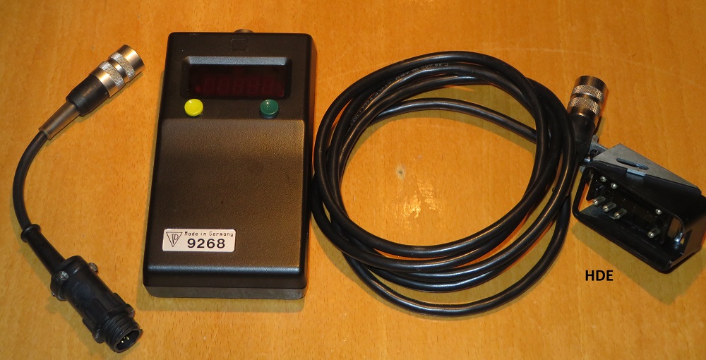
Diagnosis with tester 9268
In 1988 Porsche published WKD 494 520. A service information booklet on the use
of the DME and LH-EZK diagnostics tester 9268 which was a tool designed for use
in the Porsche 944 S and and Porsche 928 S4.
Ive rewritten all the test plans and outputs for the site. Now all you need is a
"Tester 9268" which has a microprocessor, which is responsible for diagnosing,
evaluating and displaying test results.
Fuel injection and ignition control units in 928 S 4 (LH/EZK) and 944 S (DME)
are capable of self-diagnosis beginning with 1988 models. In other words these
control units are capable of recognizing, storing and output of system faults.
Control units capable of self-diagnosis can be recognized on the changed part
numbers and a label with the designation “DIA” (capable of diagnosis). A
specially developed TESTER (Special Tool No. 92681 must be applied to read out
the control unit fault memories as well as test certain components and control
signals of the fuel injection and ignition systems.
Power is supplied to the tester from the diagnosis socket in the car via the 2
meter long tester connecting lead with diagnosis plug.
Two buttons are provided for operation of the tester.
YELLOWbutton is a SELECTOR BUTTON:-
SELECTION: Tester FUNCTION 1 “-” Tester is ready for introduction of diagnosis
and step-by-step reading out of control unit fault memories or checking of
drives and input signals.
Tester FUNCTION 2 “=” Tester is ready for selection of the next system in order.
Tester FUNCTION 3 “=” Tester is ready, for example, for cancellation of a fault
memory, testing of drive and input signals or adaption of a system.
GREENbutton is an ACTION BUTTON and is used for activation of a function
selected with the yellow button.
A different tester function can be selected by pressing both buttons (YELLOW +
GREEN) simultaneously. KNOCK REGISTRATION- Tester is ready to count the number
of “engine knocks”.
DRIVE FUNCTION TEST
The “drive function test” must be understood as the checking of the function of
various components belonging to the fuel system, which, if activated, would take
on a different operating status - for example: idle speed control ON or OFF! The
activation of different components is accomplished with the tester,
INPUT SIGNAL TEST
Certain input signals for the LH fuel injection control unit or DME control unit
are checked in an input signal test. Checking is accomplished with the tester.
SYSTEM ADAPTION
Svstem adaption (originally designated “requirement adaption” in 1988 Model
Information) is to be understood as the adaption of the idle speed on the air
flow rate of a instantaneous operating status.
KNOCK REGISTRATION
The number of “knocks” produced by an engine can be counted with tlhe tester.
Knocks could be caused by knocking combustion, e.g. poor grade of gasoline, or
mechanical engine noise, which is registered by the knock sensors.
Knocks must be counted during a test drive or with the car on a roller
clynamometer. The tester displays the number of “knocks” during 10,000 ignition
firings.
Brief operating instructions are provided on the back of the tester.
Note: TURNING the IGNITION ON and OFF will cancel the tester dislplay!
Connection in Porsche 928 S4 Cars
The diagnosis socket in 928 S 4 cars is located on the control unit holder. The
following display must appear after connecting the tester.
o 0 0 0 0 -
If not, check tester connections or power supply of car to the diagnosis socket.
Important: The battery or plugs of control units must not be disconnected prior
to a diagnosis.
After connection, turn on ignition, the following display must appear.
? 0 0 0 0 -
The ignition must not be turned off during the entire duration of fault
(diagnosis!
Porsche 928 Fault Diagnosis
Press the GREEN button until the triggering symbol appears in the “function
display”.
? 0 0 0 0 o
Diagnosis for the 1st control unit (LH) will run off afterwards.
? 0 0 0 0 -
Note: Fault code is put out continuously! If a fault is displayed.
? 1 x x x -
Press the GREEN button until the triggering symbol appears in the “function
display”. The next fault code (if applicable) will then be displayed (a maximum
of 3 faults can be displayed one after the other).
This appears if there are no faults:
? 1 5 0 0 -
Press the GREEN button until the triggering symbol appears in the “function
display”, after which - OUTPUT END - is displayed (diagnosis for LH control unit
is finished).
? 1 0 0 0 -
Note: If faults had been displayed, the fault memory in the control unit (LH)
must be cancelled!
In order to activate fault diagnosis of the next control unit (EZK),press the
YELLOW button so often, until the function symbol “=” is displayed in the
“function display”.
? 1 0 0 0 =
Press the GREEN button until the triggering symbol appears in the “function
display”.
? 2 x x x o
There is then fault diagnosis of the next control unit (EZK) If a fault is
displayed - note the fault code. See fault code list.
Press the GREEN button until the triggering symbol appears in the “function
display”. The next fault code (if applicable) will be displayed afterwards (a
maximum of 5 faults can be displayed one after the other). This appears if there
are no faults:
? 2 5 0 0 -
Press the GREEN button until the triggering symbol appears in the “function
display”, after which - OUTPUT END - is displayed (diagnosis for EZK control
unit is finished).
? 2 0 0 0 -
Note: If faults had been displayed, the fault memory in the control unit (EZK)
must be cancelled!
Cancelling the Fault Memory of a Porsche 928 S4
The fault memory of LH control unit and fault memory of EZK controll unit must
each be cancelled separately.
The code “Output End” is displayed to indicate that fault diagnosis of a control
unit has been completed.
The control unit fault memory can be cancelled to the following instructions
when this “code” is displayed.
? 1 0 0 0 - (LH)
? 2 0 0 0 - (EZK)
Press the YELLOW button so often, until function symbol “=” appears in the
“function display”.
? 2 0 0 0 =
Press the GREEN button until the triggering symbol appears in the “function
display”.
? 0 0 0 0 o
The fault memory is cancelled, if the LED goes out and the function display
changes to function symbol “-“.
o 0 0 0 0 -
Fault diagnosis of the next control unit (EZK) takes place after the fault
memory of the 1st control unit (LH) has been cancelled.
DRIVE AND INPUT SIGNAL FUNCTION TEST
Drive and input signal function tests can be carried out independently of a
fault diagnosis.
The function/signal travel of various components or electric: signals are
checked in this function test. A function is activated from the tester. The LH
control unit performs the function.
In the function test of components they must be heard or felt to be operating
and in this manner can be recognized as being electrically okay or faulty. A
faullt display is not possible via the tester, however, faulty input signals or
their wire connections will be recognized by the tester. The function test runs
off to given test steps, which are:
TEST ORDER COMPONENT/SIGNAL TEST CODE
1 Fuel injectors 1311
2 Idle speed control 1321
3 Tank venting solenoid 1322
4 Resonance plate 1323
5 Speed signal EZK to LH 1331
6 Idle speed contact 1332
7 Full load contact 1333
8 Air conditioner (AC) switch 1334
9 AC compressor clutch 1335
10 Idle speed drop for auto cars* 1336
* This test code is also put out for cars with a manual transmission, however it
must be ignored since there is no reduction of engine speed.
Drive Function Test
TEST
IGNITION TURNED OFF
Press the YELLOW button so often, until function symbol “=” is shown in the
“function display”.
o 0 0 0 0 =
Press the GREEN button until the triggering symbol appears in the “function
display”.
o 0 0 0 0 o
TURN ON IGNITION within 8 sec.! Display:
? 0 0 0 0 -
Important: The ignition must not be turned off (e.g. after starting engine)
during the entire duration of the function test!
The first test step is activated (fuel injectors). The operation of all of them
must be heard/ felt in the engine compartment.
Display: Test step code 1st test step.
? 1 3 1 1 -
Note: There could be starting problems when attempting to start the ‘engine
later, since a small amount of residual fuel is injected in this test step.
The function of test steps continues so long, until the GREEN button on the
tester is pressed again (display: triggering symbol). Pressing the GREEN button
again = test step 2 ) Pressing the GREEN button again = test step 3 )- see test
code list Pressing the GREEN button again = test step 4 ) From test step no. 5 -
speed signal - on, certain switches in the car must be operated additionally for
the function test!
INPUT SIGNAL FUNCTION TEST
Press the GREEN button until the triggering symbol appears in the “function
display”.
? 1 3 3 1 -
A display (Test Step 5) follows afterwards. Operate the starting motor about 5
seconds! (Important: Don’t turn off the ignition after starting. - The engine
will not start, since there is no injection (ti).) If the speed signal of the
EZK control unit is recognized by the LH control unit, after starting the
display with change to:
o 0 0 0 0 -
If after a test step runoff (approx. 3 sec.) the tester display does not show
o 0 0 0 0 -
there is a fault!
Press the GREEN button until the triggering symbol appears in the “function
display”. There will now be output of the next test step. - See test code list
and instructions.
All other input signal functions are tested by pressing the GREEN button again
and waiting for the triggering symbol display. After the 10th test step and
pressing the GREEN button, the fault code:
? 1 0 0 0 -
- OUTPUT END - will appear.
TURN OFF IGNITION! The function test is completed.
If faults had been detected, check the component and activation or leads/plug
connections of a component/signal travel.
Knock registration
A “FAULT DIAGNOSIS” must be carried out prior to registering the engine knocks,
in order to exclude a disturbance with influence on knock regulation.
The knock frequency of an engine can be recognized with the tester.
1 Knocking can be recognized by . . . I . . . knocking combustion (e.g. poor
grade of gasoline) or . . . mechanical engine noise.
In the load range of the engine it is operated very close to the knock limit
with the ignition curve, through which combustion knocks and therefore also
ignition timing coirrections for each cylinder occur more or less frequently.
The number of “knocks” registered by thle sensors are calculated each time for
10,000 ignition firings. The registration of knocks should only be performed, if
there are customer complaints about, for example, poor engine performance or
high fuel consumption.
Conditions: Engine at operating temperature. Test performed while test driving
the car or with the car on a roller dynamometer.
Test
Engine at operating temperature for beginning of test! Press YELLOW and GREEN
buttons together with engine running until the knock registration symbol (ready)
appears in the “function display”. The tester is now ready for counting!
o 0 0 0 0 r
Press the GREEN button until the triggering symbol appears in the “function
display”.
o 0 0 0 0 o
The tester is switched active - ignition firings are being counted without
displaying them on the tester.
If knocks occur, they will be displayed.
Knock registration must be performed so long, until the function display changes
from triggering symbol to the knock registration symbol. This is always the
case, when 10,000 ignition firings have been completed. All occurring knocks are
added together and displayed as a final result.
If knock registration has to be stopped, the YELLOW button must be pressed until
the display shows this:
o 0 0 0 0 r
To start up knock registration again, press the GREEN button until the
triggering symbol appears in the “function display” again. In order to leave the
“KNOCK REGISTRATION” program, the GREEN and YELLOW buttons must be pressed
simultaneously until the function symbol “-” appears in the function display.
o 0 0 0 0 -
Note: A knock display of > 5.0 (50) indicates a fault, if the test hlad been
carried out under normal operating conditions.
System Adaption
Sytem adaption can be performed with this tester. In other words the electronic
idle speed control in the LH control unit is adapted to the actual air flow rate
and instantaneous engine status.
Requirement: ENGINE AT OPERATING TEMPERATURE!
IGNITION TURNED OFF!
Press the YELLOW button so long, until the function symbol “=” appears in the
“function display”.
o 0 0 0 0 =
Press the GREEN button until the triggering symbol appears in the “function
display”.
Now start the engine within 8 seconds. Let the engine run at idle speed until
code “system adaption” appears.
? 1 4 1 1 -
Let engine run at idle speed at least 30 seconds!
System adaption is completed afterwards.
Switch off the engine.
END OF SYSTEM ADAPTION!
Fault Codes - LH Control Unit
1500 No faults stored in memory
1000 End of output
1111 Power supply voltage too low/high l6V
1112 Idle speed contact, Ground short
1113 Full load contact, Ground short
1114 Engine temperature sensor, Ground short/break
1121 Air flow sensor
1122 Idle speed control
1123 Oxygen sensor control recognizes
excessively rich mixture
1124 Oxygen sensor control recognizes
excessively lean mixture
1125 Oxygen sensor, Break/faulty sensor
* A 2 standing for “sporadic fault” could also appear in the 2nd digit of the
fault code (not for fault code 1500 or 1000)!
Fault Codes - EZK Control Unit
2500 No faults stored in memory
2000 End of output
2112 Idle speed contact Ground short/break
2113 Full load contact Ground short
2114 Engine temperature sensor Ground short/break
2115 Idle speed and full load contact Ground short
2121 Load signal from LH control unit
2126 Transmission protection switch Ground short/break
2131 Knock sensor I
2132 Knock sensor I I
2133 Knock control in control unit
2134 Hall signal
2141 EZK control unit
* A 2 for “sporadic fault” could also appear in the 2nd digit of the fault code
(not for fault code 2500 or 2000)!
Drives and input signals
1311 1 - Fuel injectors
There could be starting problems after this test in spite of the brief
activating frequency.
1321 2 - Idle speed control 1322 3 - Tank venting solenoid 1323 4 - Resonance
plate 1331 5 - Speed signal from EZK control unit to LH control unit
Operate starting motor about 5 seconds until LED or numbers 3n tester go out.
1332 6 --- Idle speed contact
Operate accelerator pedal lightly. After about 20 mm travel the LED must go out
and after about 3 sec. display “0 0 0 0 -” must sppear on the tester.
1333 7 - Full load contact
Accelerator pedal to full load. LED must go out and after about 3 sec. display
“0 0 0 0 -” must appear on the tester.
1334 8 - Air conditioner activation to LH control unit term. 15
Turn on air conditioner. LED must go out and after about 3 sec. display “0 0 0 0
-” must appear on the tester.
1335 9 - Air conditioner activation to LH control unit term. 14
Turn off air conditioner. LED must go out and after about 3 sec. display “0 0 0
0 -” must appear on tester.
1336 10 - Speed reduction for cars with automatic transmission (not for manual
transmission cars)
Move selector lever from P or N to a driving range position. LED must go out and
after about 3 sec. display “0 0 0 0 -” must appear on tester.
1000 END OF OUTPUT