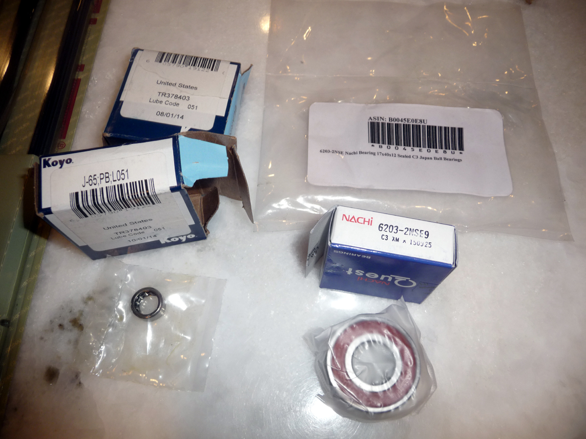
If you have access to a vise, an R&R of all 6 bearings is about 2 hours plus $50
in bearings- One 6203V, one B-188, and four J-65's.
I got a little anxious during the disassembly and forgot to take pictures. I hope I made up for it with the pictures of the reassembly.
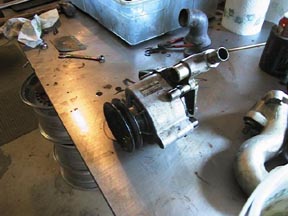
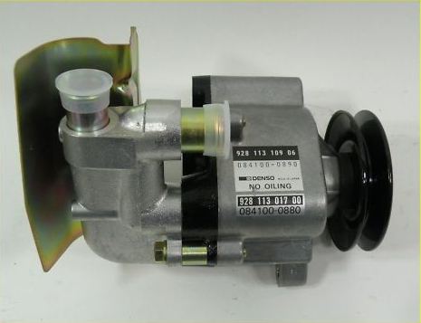
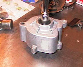
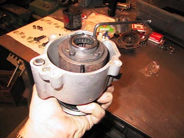
This is a photo of the air pump just removed from the car. When done it will look the same only cleaner and the rumble of the bearings will be gone.
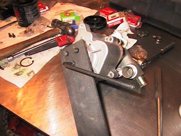
I made a puller to remove the pressed on bushing which the pulley bolts to. It is a piece of 1/4 x 2 inch steel about 12 inches long. Three holes were drilled to match the threaded holes in the bushing. By gradually tightening the bolts and installing a 1/4 inch nut under it after bottoming out I was easily able to remove it.
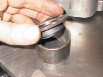
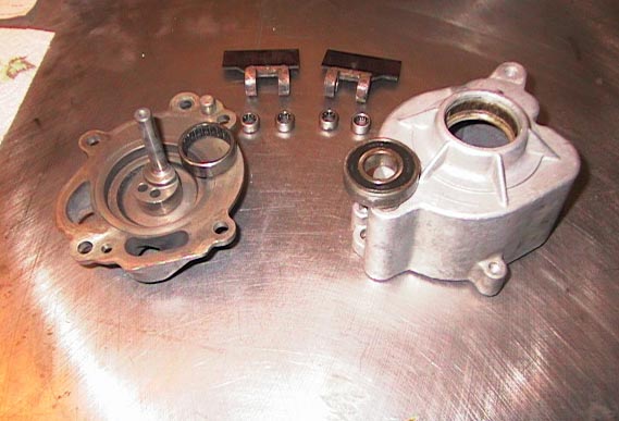
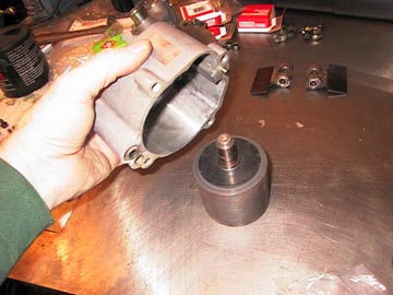
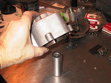
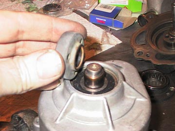
This is the rear bearing and it's housing. To remove the bearing I cut a piece of tubing just slightly larger then the bushing portion of the housing.
By resting the housing on top of the piece of pipe I was able to pound out the bearing with a drift and hammer.
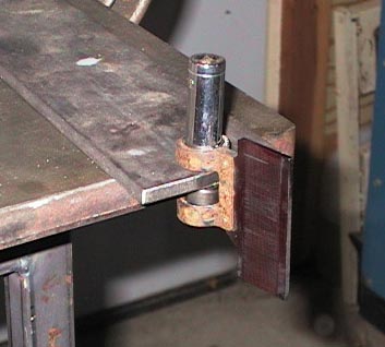
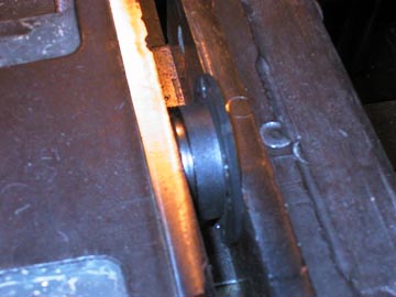
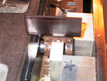
By drilling a hole just large enough for the small "paddle" bearings to slide through in the other end of my puller tool, I was able to pound out the four smaller bearings. Great care is needed here as the paddles do look like they could be easily ruined.
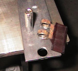
This is what the tools used to pound out the small bearing actually are. NOTE how close to the edge the hole must be for the bearings to go through, also that the drift to remove the bearings is just a 3/8" drive socket. Non of the bearings were dificult to remove.
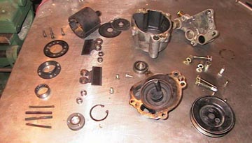
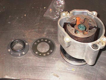
This is what you have when done with the disassembly. A few more parts then I expected!
OK! All the parts are cleaned up and ready for reassembly. These are the six new bearings ready to be pressed into place.
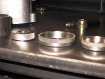
I figured I'd show off a couple of special tools I keep, and the new tool I made for this job. The two to the right are old front wheel bearings which I ground the small side edge down on. Once you have the new bearing race down to the wheel hub, you can use these to pound the race in the rest of the way. They won't get stuck in the hub when you are done. I did the same with the old front bearing on the air pump.
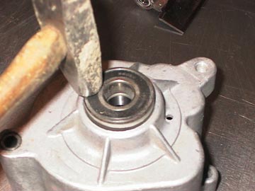
If you look close you can see the new bearing under the old bearing in this simple proces of installation. just keep it all strait as you pound it into the case. You will here a change in sound when you reach bottom and don't pound to hard, it is aluminum you are pounding that bearing into.
I used my Bridgeport vise to press some of the bearings into place. It is a very easy way to keep things strait. You can probably use a bench vise, but I would find something flat to put in the jaws so that the sarated teeth don't push into the bearing housings.
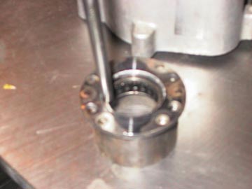
Here I am pressing in the small bearings, being very carefull not to put forces on anything but the bearing and it's housing.
I am about to place the housing over the rotor.
Then the rotor goes over a large 1/2 inch drive socket. It didn't look like a good idea to put any strain on the rotor itself.
Using a socket slightly larger then the drive shaft of the rotor I pounded the case and bearing onto the rotor assembly. Again it was easy to tell when I made bottom by the change in feel and sound.
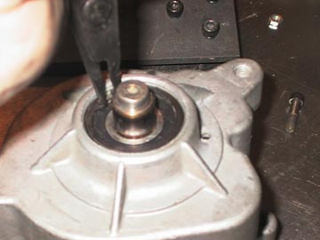
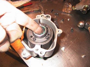
Don't forget to reinstall the C-clip. Make sure it went down into the groove so that it doesn't float out down the road sometime.
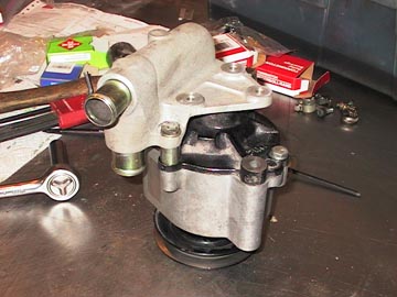
Now we have to press on the bushing for the pulley. This baby is really on there. I was surprised what it took to do this.
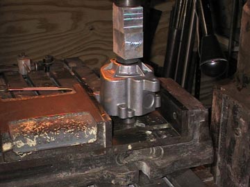
I put the large socket on the bed of the vise, the rotor on the socket, the bushing on the shaft, and a block onto the bushing. I then cranked up the bed of the mill to press on the bushing. I'll never get a job working for David Sheafer after he sees this! Maybe I should buy one of those small presses someday.
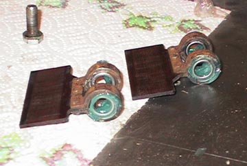
This is a view of the two paddles to remind you to put some grease in there. I used high temp wheel bearing grease.
Installation of the paddles is pretty simple, one faces one way, one the other way.
This shows the pressing into place of the wiper and it's spring. The pointed edge of the wiper goes against the paddle. The spring tips go against the wiper and the spring center goes against the rotor.
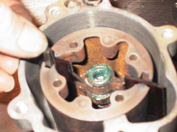
This one is interesting. If you look at the gasket one hole is smaller, and at the rotor, one relief area is smaller. I don't know why, but it seemed like a good idea to line them all up.
This is a good note too. When you tighten the allen bolts on the rear bearing plate, don't hold the pump housing with your other hand. It would be a good way to destroy the paddles. Hold the pulley to tighten with.
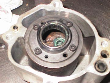
Don't forget to grease the rear bearing before final assembly.
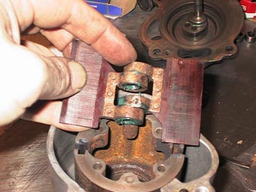
Here is a tough one. You have to get the bearings lined up to put the rear housing on. I positioned the rotor so that one paddle was fully extended and one was all the way into the rotor.
WOO-HOO, I took a big jump on you guys, sorry. After sliding the rear cover on don't panic if you decide to spin the unit before you snug down the bolts, you will hear lots of scraping untill everything is tight and strait. AT THE SAME TIME it is a good thing to do some spining as you tighten it up. If you did something wrong this is where you will crush ad destroy the paddles.
Send comments to: markg@compu-motion.com
____________
I think the bearing
numbers should be like this:
1x 6203-2RS ball bearing front side
1x B-188 Timken needle bearing rear side
4x J-65 Timken needle bearing on the fan/paddle arms
Regards,
Theo
http://928gts.jenniskens.eu
======