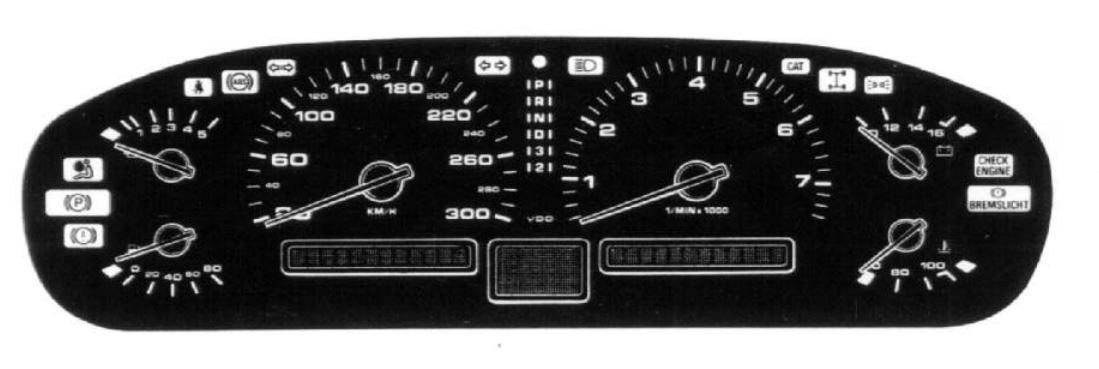
Digital instrument
panel PCB. (V long)
--------------------------------------------------------------------------------
Recently I carried out some repairs to my instrument cluster including
replacement of the printed circuit boards. I was most surprised to find that
very little information was available on Rennlist or elsewhere so with the help
of several other Rennlisters I’ve done some research. I’ve collected quite a bit
of material and would like to record what they and I have learned for the
archives. It is applicable to ‘89 and later digital instrument panels.
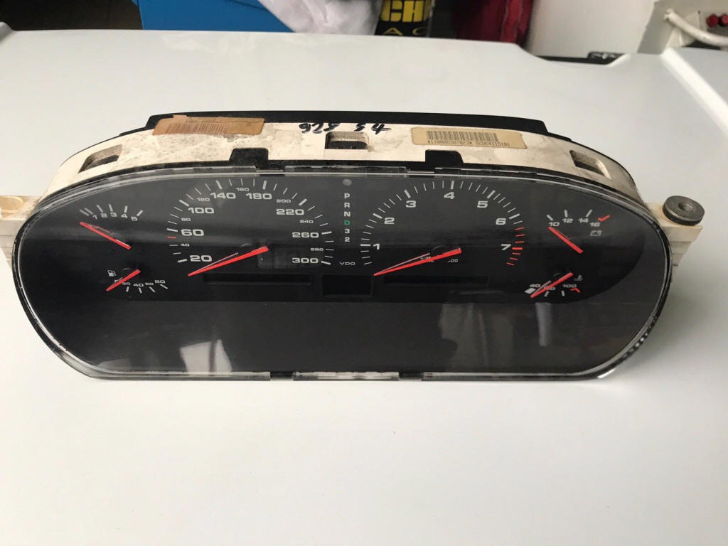
The digital instrument panel introduced in 1989 is of VDO manufacture. It
incorporates the warning system adapted from previous years and the trip
computer but it also passively records data, especially fault information on
several vehicle systems, eg ABS, Coolant pressure, Oil level etc. The fault
information can be read in summary directly from the display or more
comprehensively by a Porsche workshop’s diagnostic equipment. Instructions for
the use of this feature were published in the 1989 workshop document WKD 495 821
entitled ”Diagnosis of the instrument cluster”.
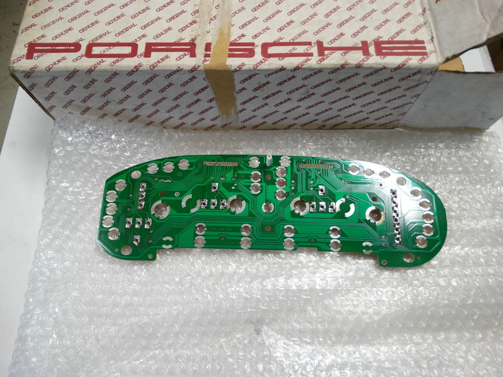
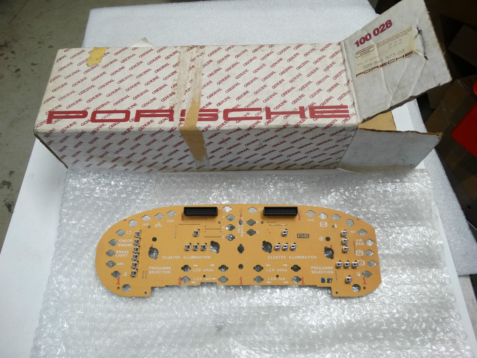
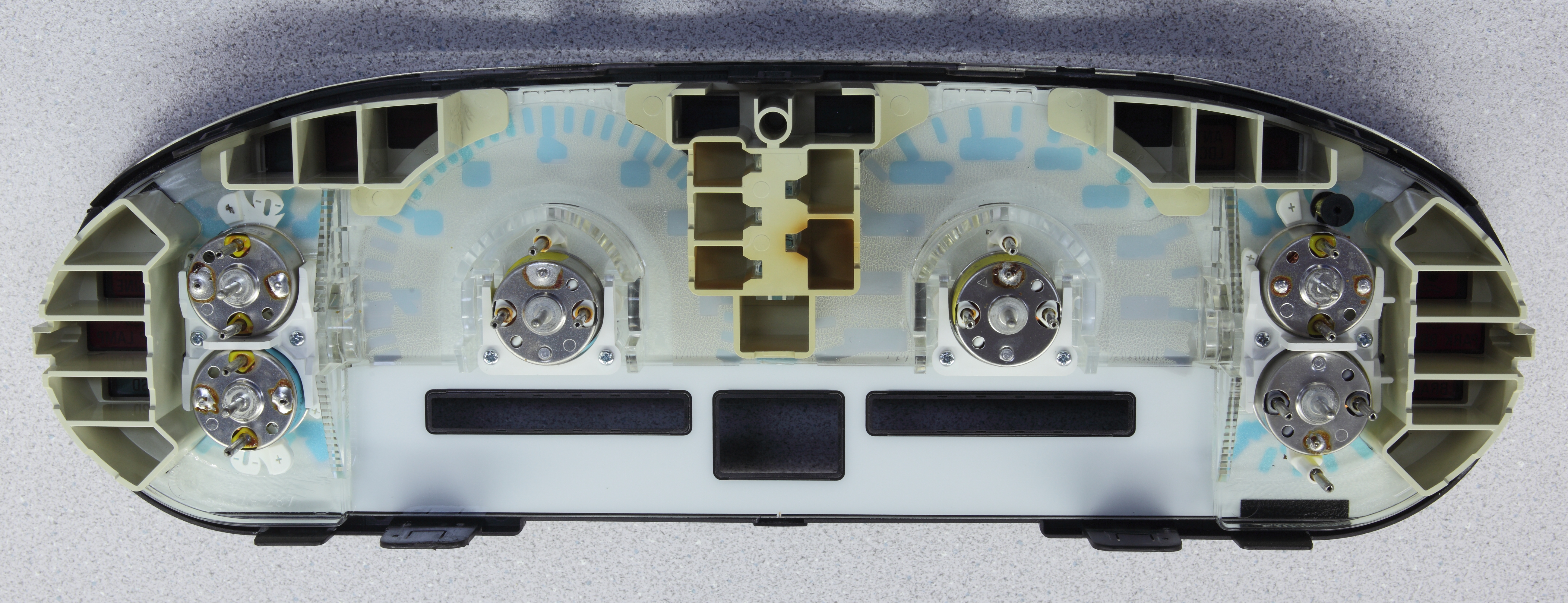
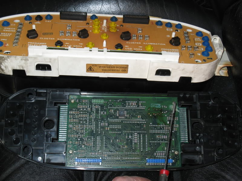
The heart of the digital instrument cluster is the printed circuit board (PCB)
of which about 30 variations were produced. They were progressively developed
with successive model years, each with a different part number and a software
‘level’ tailored to the various requirements of the countries of intended sale
and the specification of the vehicle. For example, manual or auto, MPH or KPH,
airbag or not, Saudi Arabia speed warning buzzer or not, etc. For this reason
the boards are not completely interchangeable.
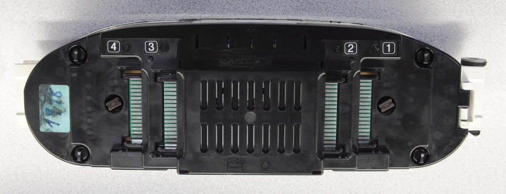
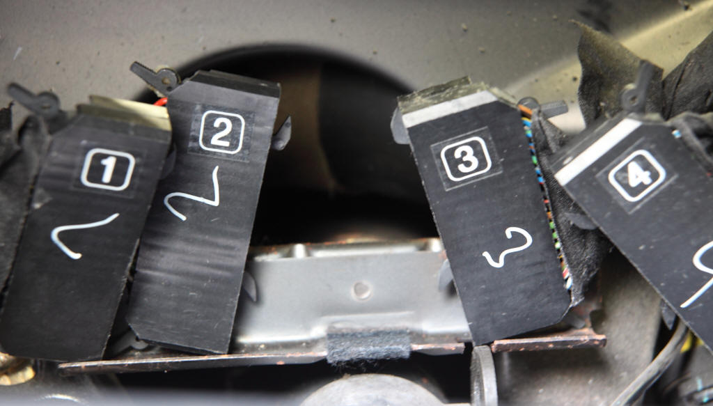
The PCB is in two sections joined by flexible links and is fitted into the black
plastic housing which forms the rear of the instrument cluster. The innermost of
the two sections is glued into place and is not easily removed from the housing
though the housing and PCB assembly can be unhinged from the main section of the
instrument cluster. This is also the method by which the instrument bulbs can be
replaced once the pod and cluster have been removed from the car. They cannot be
changed in situ.
Failures of the PCB are fortunately not common. They can be caused by damage to
sensors or other hardware outside the instrument cluster and by transmitted
shock from severe impacts even if the instrument cluster itself is not directly
involved. Spontaneous failure has also been reported. Symptoms include
inoperative or erratic gauges, inoperative, always-on or flickering warning
lights, failure of the trip computer and/or warning system, and total or
intermittent blackout of the panel. It should be pointed out that several of
these symptoms can also be caused by loose or dirty edge connectors on the PCBs.
Due to the sandwich construction of the boards some circuits are embedded within
the board material and are inaccessible. A competent electronic workshop could
probably effect repairs to the external components but Porsche appears to have
published no documentation or drawings of the circuits within its technical
literature and at present replacement of the circuit board is the best option.
New boards are in very short supply. At the time of writing (Oct ‘04) only four
boards remain in stock in Germany at a cost of about $1000 each though
individual dealers may of course have stock of their own. This remaining stock
are of P/N 928 641 991 30, a late model configuration which should hopefully be
backwards-compatible with most others.
Language and value changes
Depending on the software status (level) of the circuit boards installed certain
information displayed on the instrument panel can be changed to suit the owner/driver.
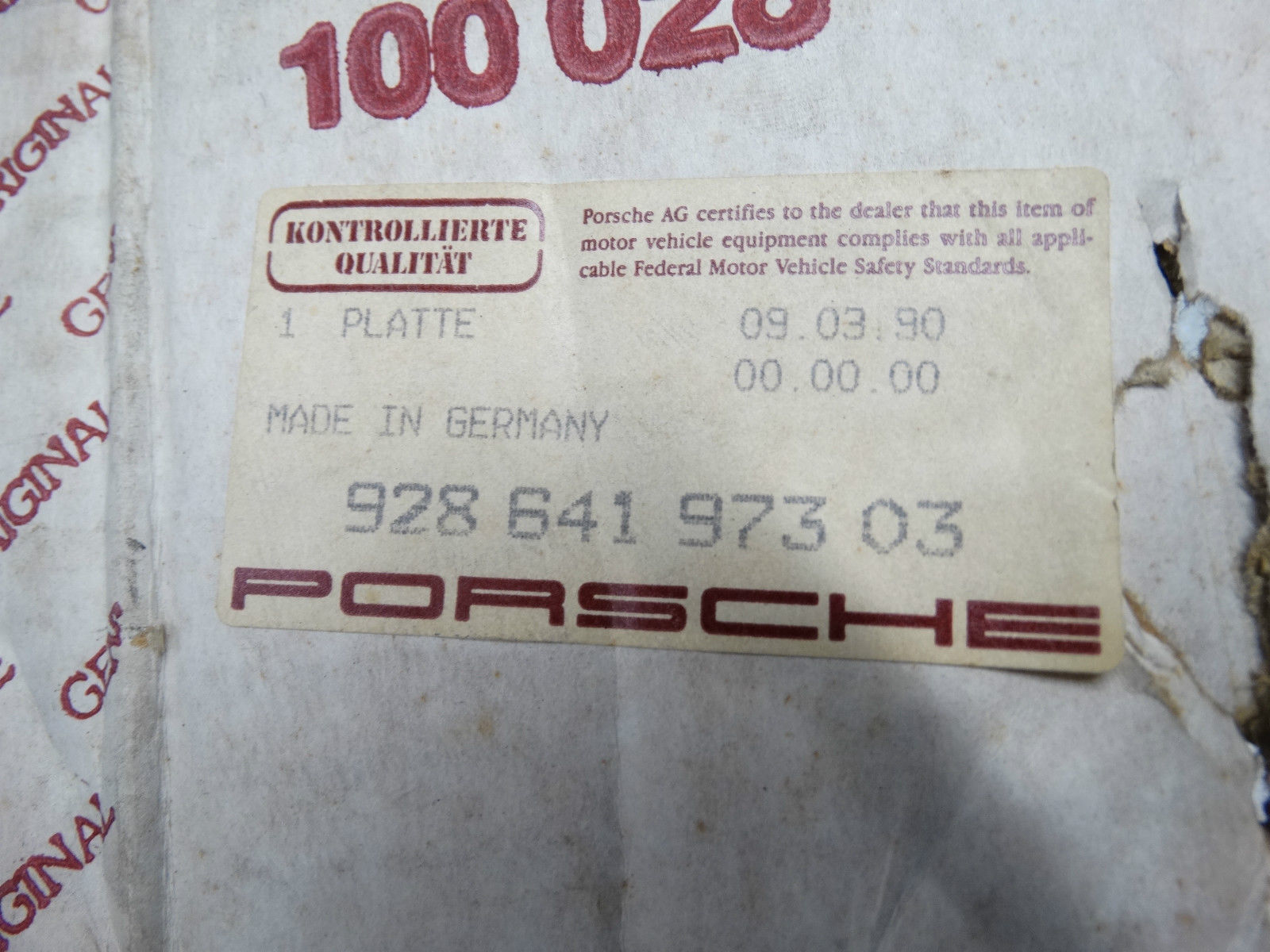
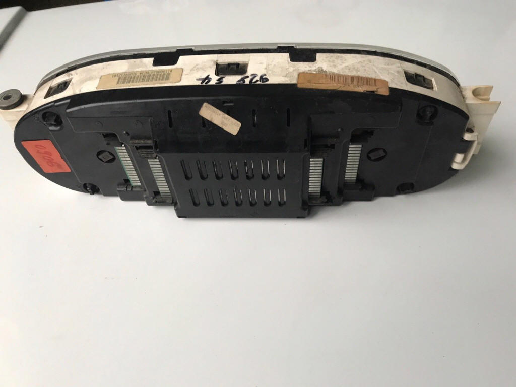
The software status is shown in the square centre box of the computer display
when the special tool 9293 or jumper, described later, is fitted. It is also
printed on a rectangular paper label stuck on the back of the instrument cluster
and inside between the two circuit board sections.
The digital panel was first introduced in 1989 with “software level K18”. The
dashboard language could be supplied in German, French, Italian or English and
could NOT be changed but on US market cars the units of measurement could be
changed from Metric to Imperial and back by selecting the appropriate display
function then pulling the operating stalk twice within one second.
From MY 1990 and software level K25 the language could be changed by a Porsche
dealer by the use of special tool 9293 fitted into the19-pin diagnostic socket
under the floor panel between the passenger’s seat and the door. In fact the
special tool is merely a bridge between pins 5 and 13. A wire jumper will
substitute. For those wishing to do this the language change procedure is.
Turn on the ignition
Fit tool 9293 or the jumper (NB, it won’t work if the jumper is fitted before
the ignition is turned on)
Hold back the control stalk for 3 seconds until “LANGUAGE” appears in the
display.
Pull the stalk sequentially to scroll through the four available languages.
Turn off the ignition and/or remove the jumper to store the language displayed.
The language and the selected units of measurement revert to the default if the
battery is disconnected or the instrument power supply is lost by other means.
From MY 1991 and software level K26 the selected language and units were no
longer lost when the power was disconnected. If a new circuit board was fitted
K26 also provided for the reading of the odometer display to be set to the
vehicle’s correct total distance travelled but note that this only applies to a
factory new circuit board or one with less than 250 miles or km on it. The
procedure to do this is covered under “Specific Functions” as described (badly)
in the document ‘Diagnosis of the Instrument Cluster’.
The final variation of the software, level K29, was introduced in the first GTS
of ’92. Curiously this limited the diagnostic scope of the instrument cluster to
internal faults within the instruments themselves.
The shortage of new replacement circuit boards is a concern as is the absence of
circuit drawings or other technical details which would allow users to have
their boards repaired. For those contemplating a PCB replacement the above
information should, for the immediate future, help to identify a suitable used
component.
You'll find the software level on the small white paper label with rounded
corners on the back of the cluster incorporated in other digits. It says
INDEXHK25(or whatever, that's your software level,) followed by a seven digit
number. There are other labels on the cluster, one of which which shows the 928
part number for the cluster AS A WHOLE. I don't have a cluster with me now but I
think that one also has a bar code and straddles the joint between the white and
black housings. As for the wires soldered on, Schocki has a theory that you can
change the language that way but we've never proved it.
Colin, 89GT. With thanks for input from John Speake, Roger Tyson, Wally Plumley,
Doug Hillary, Tails, Schocki and others.
=========
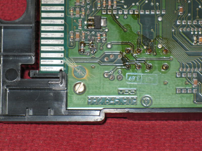
Inst board wiring:
Those wires you see running on top of the traces of the board represent a
modification or revision that was applied after the run of boards was etched &
silkscreened. Sometimes it's possible to fix a problem with microcode (PROM
code), other times, a change to the circuitry is required.
It's one of those dirty little secrets in the computer business that happens all
the time. Look near the paper tag with the K18 or K25, and somewhere around you
will also see either a paper tag, or possibly an ink stamp with words like "REV
-04" or "VER -58" or something like that in German for revision or version.
While you're looking about in there for the codes on the paper tag, find some of
the writing on the chips on the board and either post or PM them to me. I'll try
to cross ref them. Try to get all the writing including the MFG stamp, which may
look like the state of Texas for a TI part, or a bold font M for a Motorola,
Siemens uses a big S with a box around it.
So, what happens is, the boards are silkscreened and tested then put into
production. At some point Franz realizes that he didn't add a signal to some
gate that will do something when a certain set of circumstances occur. It's
typically pretty obscure, and you wouldn't find it in the normal course of
operation. So, a sustaining engineer develops a board rev spec, and someone with
a soldering iron and a spool of 32Ga wire starts connecting lines. When a board
comes back for repair, or in the case of a serious mistake, all the boards may
be recalled and rewired (rare).
Also, as you mentioned, some revs of boards are meant for certain applications.
It's entirely possible that the board in your car from Canada (eh) is exactly the
same as the board from US, but the trace wires have been ADDED to disable the
SAE measure display. Again, a car destined for Canada had a special stop at the
wire station to add these wires and defeat the functionality that was built in.
Airbag Malfunction display;
I think my board is correct in saying that I have a malfunction. Since the
control unit is in the center console, and my wiring for the center console has
been seriously tampered with by some gorrila attempting to fit a stereo, it's my
opinion that the wiring fault exists in the center console where it serves the
airbag control unit. I checked the bags carefully and they haven't deployed, so
it must be in the wiring, or control unit.
RDK;
Yes, I've heard of all the problems with the RDK, and the simple defeat of the
system with a wire from pins 5 to 13 of the RDK control unit. I may go that way
too, but first I'll look into getting it fixed if it's not to big of a job. I
suspect faulty wiring from the harness at the LR sensor, up the suspension and
then to the harness mating plug near the diff. Heck it might be just as basic as
cleaning the RDK knob on the rim, and the sensor on the hub. They have some kind
of proximity detection going on, and cleaning it may do wonders for the sensing
circuit of the detector.
__________________
Doc 90GT
-----