
Since I get many questions about the fan controller operation I made a simplified diagram... ahum. But the good news is, that it is easy to see what everything does using some color in the lines.
Both fans have a separate wire going to ground point II which is located at the side wall passenger side (LHD) close to the top of the radiator side tank.
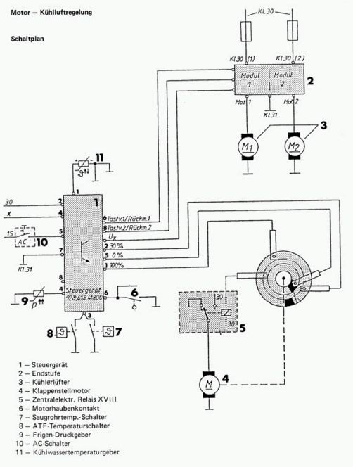
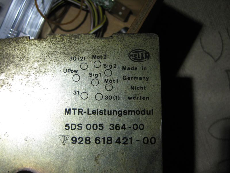
I once had a problem with a friends car. He had one fan running regularly at max rpm and the other kept silent. Fan was ok, both, as was the fan power stage and the wiring, power fuse, etc. Unplugging the round connector on the power stage and connecting the 12v power supply to the fan power (wire bridge) made both individually run perfectly. Funny is that there is only Tastv../Rückm..signal that controls the fan speed... of both fans independently... but is also a sense signal. Funny business. Turned out the controller was bad and apparently a problem at the feedback-line in the controller makes the power stage keep one fan off and thus go into emergency mode (turn one fan on fully, mot 30% or 60% or so)
Replaced the controller, problem gone.
Theo
=====
One fan runs fast,
other stays off>>> all is off when I turn ignition off.
First: there is no short circuit ion the power stage cause the fans stay off
when ignition is off.
Second: the right fan seems to work.
Third: the left fan seems defect.
Troubleshooting:
Step 1: check if the fan itself is ok. Do this: unplug the connector at the
power stage. The connector has numbers on it. Take a decent wire to make a
jumper wire. Avoid risk on short circuits. Carefully (!!!!, this is 12v but
maybe 10 Amps) connect Pin 1 to pin 8 to power up the Fan1. Fan will run max
power, so watch out for anything in that area like wires. Next connect Pin 4 to
pin 5. The Fan2 will run. If that works, you verified that the fans are
operational, and the problem moves to the power stage or controller box.
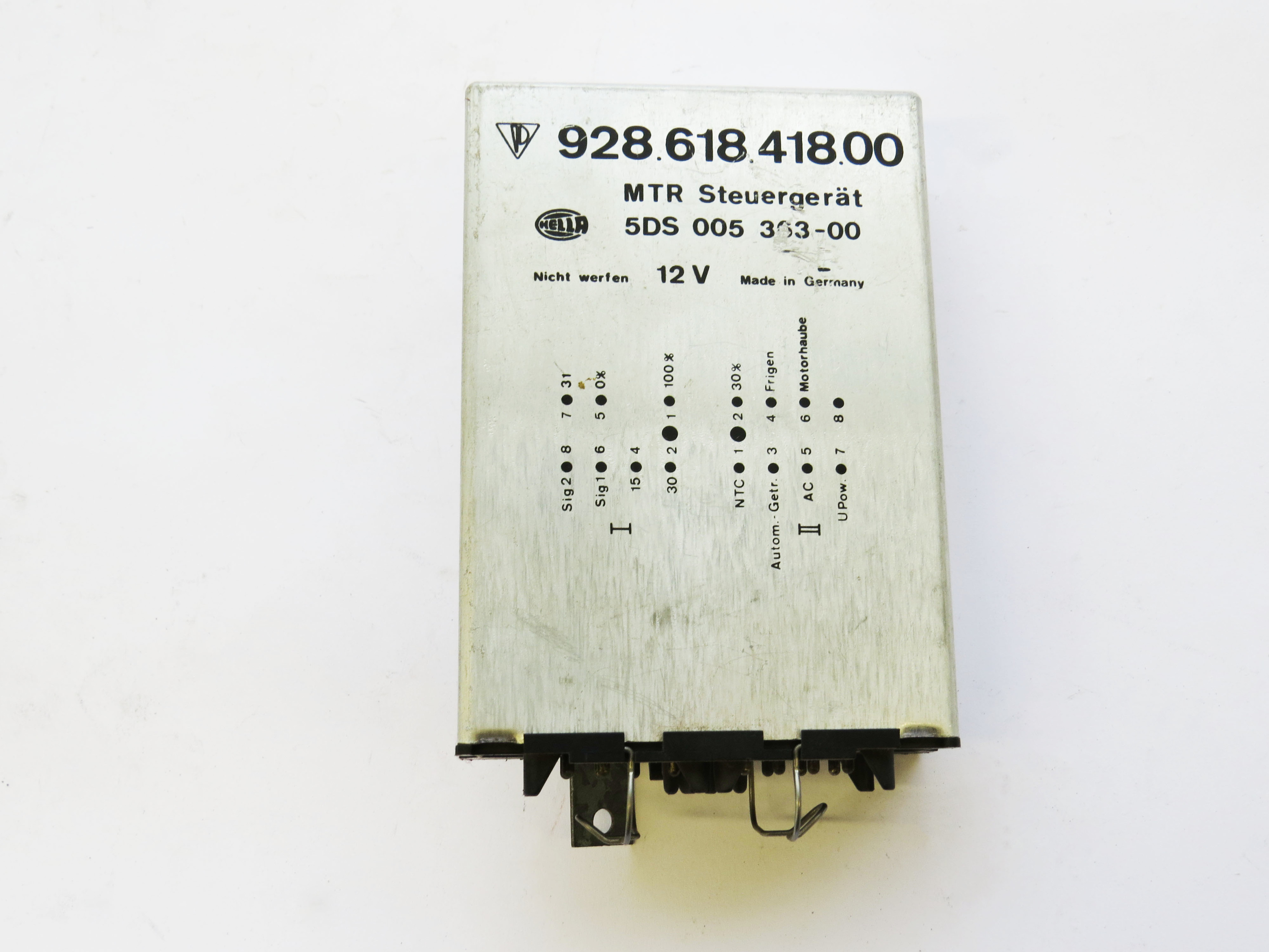
Step 2: look at the connectors at the pass side Controller box. Two flat
connectors will be there. Find in connector 1 wires 6 and 8 (6=blue and 8=green)
and on connector 2 wire 7 (grey). I think the wire 7 is the on signal, a Ux
signal to the power stage to send electronics power to the fan power stage (not
the fan main power).
The other two are controller/return signals. Check voltage on wire 7. You should see a
9v
or similar when you activate the AC. The Sign 1 and 2, wire 6 and 8,
should carry a voltage. If no voltage is there on one and the other has 12v, I’d
suspect the power stage. But I was also puzzled once that it turned out to be
the controller itself, blocking the signal….
=======
The fan power needs are quite large:
Fan reads about 17 Amps steady load, inrush/surge was less
than 20 Amps.
Unplugged both fuses so the controller would see a fault when testing just one,
and force high speed. AC running to get the fans on. Middle speed is about 10
Amps running.
====
Te coolant sensor signal feeds to pin #1 of the Fan Controller module. It tells the fan controller to run the fans as temperature has reached 80 degrees or so (look for the exact figure). Disconnecting the sensor, short wiring the sensor will both make the fan controller go into full power as it would like to get precise information (analog value of the resistor).
Theo
====
Dear Theo,
yesterday night I took the car to go to my usual pub....When I came back home
fans started again...
this time the radiator sensor broke.
Using your essential site I unplugged each sensor and attached a proper resistor
on each connector, in order to give the control unit the "feeling" that engine
was cold.
When I inserted the 3800Ohm resistor in radiator sensor plug , fans stopped working.
Close bonnet, fans were off....connected a 1100 ohm resistor and fans started
running.
I am very happy now. I will order a new sensor (VDO, no compatible stuff
available so I will buy it from dealer) end I will change intake air sensor and
the NTC sensor for the management system of the engine. Just to be sure.
With best regards,
Francesco From Italy
======
The low/high pressure switch (is
actually an on/off switch) can be bypassed so that the compressor starts running
again. Using this briefly usually verifies that the pressure is low and the
system would probably work when refilled. A high pressure condition should be
easy to see, the system likely is very hot. The low/high pressure switch
disconnects the compressor so that it stops running if pressure rises above or
below some limit.
The high pressure analogue sensor is to notify the fan system and turn on full
speed if required. It is independent.
Theo
=====
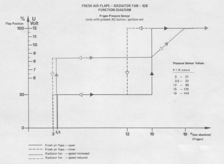
The analogue pressure Sensor at the AC dryer assembly controls the Fan activity. Pressure in the AC when not running should be about 4 bar (60 PSI) measured at the pressure port, and this relates to a sensor value of 40 ohms (values vary based on temperature, filling of the system, type of refrigerant). Fans run at intermediate power when the engine is not running but ignition and AC is turned on. When the AC is turned on and the compressor runs, interior fans to max cooling, pressure rises a bit and the sensor reads 80 ohm. At full heat the pressure may rise up to 15 bar, the sensor then reads about 120 ohm, and the fans go to max power to cool down the refrigerant and case pressure drop.
When the sensor signal is not connected to the controller (wire disconnected at the sensor) the controller thinks the pressure is way up and turns the fans to their maximum power to cool down the AC and make pressure drop.
regards
Theo
1992 928 GTS midnight blue
-----
With the ignition switch on, the fans are triggered on at low speed at
approximately 78 deg C coolant temp, and reach full speed at approximately 95
deg C. They are triggered on at low speed at approximately 110 deg C
transmission fluid temp. They are triggered on at low speed at approximately 3
bar Freon pressure, and reach full speed at approximately 20 bar.
With the ignition switch off, the fans are triggered on at low speed at
approximately 85 deg C coolant temperature, and off at approximately 83 deg C.
They are triggered on at approximately 87.5 deg C air temperature in the intake
plenum, and off at approximately 82.5 deg C.
Wally Plumley
====
If you unplug the connectors at the controller box (the one next to the passenger seat for LHD) and then plug in only the connector #2 the fans go into emergency mode. This would mean that both fans start running at full speed.
** I never tried this, so the information is not verified.
regards, Theo
1992 928GTS midnight blue
the Netherlands