Lots of musings and
thoughts being thrown on a topic which we've researched extensively. Our
research was then used to come up with the 928 Super Clamp to stop the drive
shaft pull out problem at the front flexplate which can lead to 928 engine
thrust bearing failure (TBF). I will try to keep it short and hit the high
points in order to explain this situation concisely.
1. When Porsche first devised the auto driveline they used washers, a bearing
and a circlip at the front of the older 25mm drive shaft to help set the correct
distance between the flywheel and flexplate. These parts can be seen in the work
shop manuals (WSMs). The correct distance which was to be calculated by the
mechanic in the field, would have the flexplate set a bit away from the flywheel
and when the flexplate was clamped to it, there would be a bit of rearward pull
on the flywheel.
2. Porsche learned of problems with their WSM instructions since mechanics were
not correctly setting this distance and some customer 928s were returning with
TBF. Porsche then sent out there driveline engineer on a world tour to teach
Porsche techs how to properly set this distance.
3. Sometime in 1984 Porsche stopped using the bearing, washers and circlip
arrangement at the front of the drive shaft and merely had the field techs just
clamp the front flexplate clamp as the last step after a TT change out. This
change is found in the WSMs. However the front flexplate clamp was not designed
to hold onto the drive shaft by itself.
The front bearing, washers and circlip aided in this and when they were taken
away it is our opinion Porsche should have changed the design of the front
flexplate clamp.
4. Then Porsche came out with the 85-86 32 valve 928s which saw an increase in
horsepower and torque. This further compounded the problem since the extra
torque now twisted the drive shaft even more and the front clamp could not hold
the drive shaft. Porsche started seeing a problem with this and instead of
focusing on the clamp, they instead increased the diameter of the drive shaft
from 25mm to 28mm sometime in 1987. I was told by the 928 Porsche drive line
engineer this was done to handle the increased torque. However it's interesting
that although the 5 speeds saw the same increase in torque, it's drive shaft
remained at 25mm. It is our opinion that Porsche was trying to control the drive
shaft pullout by increasing the drive shaft diameter.
5. Unfortunately this did not stop the problem of drive shaft pullout.
But it did give the 928 automatic drive line another failure point since
Porsche, keeping it's old clamp design for the 25mm drive shaft spline, had to
neck down the 28mm drive shaft back down to 25mm causing a stress riser at the
neck down point. This has caused 28mm drive shafts to shear for owners in the
field.
6. We looked at many different solutions for this problem and after testing a
few, we came up with our Super Clamp design. It is *not* the one that Theo has
shown. It is totally different and attaches at the front flexplate with no
modifications, can be used with both the 25mm and 28mm drive shafts and clamps
onto the drive shaft extremely well. This has stopped drive shaft pullout at the
front flexplate.
Hope this helps with your discussions,
Constantine
Black Sea R&D
=====
Thought this was a understood point but I guess it's still in contention.
The drive shaft twists under load and shortens. It is due to it's design as a
approximately 1 diameter inch bar which is pretty long. It's also called a "prop
shaft." This is used in other applications to include the boat industry. That's
why Porsche placed a flexpate at the flywheel to allow for this contractive
force.
The front original flexplate clamp cannot alone stop the pullout of the drive
shaft and it allows it to be pulled out a bit each time until it finds an
equilibrium point. The contractive forces are much more than the subsequent
pushing of the relaxed shaft and so gets hung up by the front flexplate clamp.
The equilibrium point is usually seen as a 2mm-4mm rebound of the flexplate back
unto the drive shaft after the front pinch bolt is loosened.
The only way this type of drive shaft will lengthen is when it deforms and just
before it fails, just like when you bend a paper clip back and forth and break
it. If you measure it just before the break it will be a bit longer. This
however is not what causes most of the found forward pressure at the front
flexplate in 928 automatics.
During our study we looked at the C-5 Corvette driveline to see what they were
using. They have a hollow large diameter tube as their drive shaft and there is
a rubber coupler between the drive shaft and flywheel which takes up rotational
stresses but not contractive forces since there are none. They also experience
TBF but due to heat expansion of their drive line. After a TT change they must
run the car up to temperature then let it cool down and reposition the running
assembly.
Last point, having any forward load unto the flexplate and ultimately the thrust
bearing is bad. It will prematurely wear the engine thrust bearing and when that
happens is any one's guess. That's why Porsche wanted *no* front load at all and
devised the initial circlip, bearing and washer affair at the front of the drive
shaft to have a slight tension pulling back on the flywheel. I have talked to
many owners who have suffered TBF, a lot more than I care to have known about.
Not everyone who owns a 928 is on Rennlist.
Cheers,
Constantine
=========
It seems very unlikely that the shaft shortens that much. 4mm flexplate offset
into engine direction means that the shaft may be shortening as much as 8 mm
before pulling out more into the transmission direction. no no... it must be
something else.
=========
A wobble in the flex plates fits the ideas I've accepted -- it would affect the
clamp at between about 10Hz and 100Hz; it would affect the forward end of the
shaft much more than the rear end; it would not involve special loads or
movement on other parts of the car; it would be addressed by a strong clamp such
as Theo's or Constantine's; and it might generate a force in one direction
(towards the flex plates, or towards the un-torqued portion of the splined
fitting) -- but I can't think of a way to verify this one.
Ray
==========
Actually I thought of a way to verify this, or something very much like it.
One problem with the test setup that is being suggested is that for the amount
of movement needed to be shown there will need to be in the millions of
revolutions. Another problem is that with the small amount of shaft that is
being suggested the amount of movement will likely be much less than in real
life mainly because of the weight of the shaft, which I think plays into the
equation.
What I did a few days ago while this discussion was going hot and heavy was set
up an experiment in my lab (shop) where I found a piece of aluminum round bar
stock about 3 and a half inches long and I drilled a hole through it long ways
to just under 3/4 inch. Then I intended to ream it to exactly 0.750 inch, but my
reamer was too big to go in my tail stock chuck on the lathe, so I put the work
piece in my mill vise and chucked the reamer in the mill and reamed the hole
there.
Unfortunately (or maybe not) the hole did not come out quite precision in that
is is centered on one end but about 3 or 4 thousandths off center at the other
end. I put it in my lathe that way and proceeded.
Next I found a piece of stainless steel heavy wall tubing about 18 inches long
that was laying there and slipped it in the hole in the "body" piece I now had
in the lathe. I put it about midway on its length in the body piece. I turned
the lathe on at about 400 rpm with the lathe turning toward me--as if making a
conventional cut of the front of the body. That was with the lathe turning
counterclockwise when viewed from the work position, just as if looking forward
at the flex plate from behind the engine, and with rotation the same as the 928
engine.
At that rate of rotation the stainless tube gravitated out of the hole in the
body piece about a half inch in about a minute. Then I reversed the rotation and
the tube gravitated back the other way into the body about the same rate.
I reversed the body piece in the lathe and did the same thing and had just about
the same result. This time however. I think I had the centered hole facing me
and I think the rate of migration back into the lathe with reverse rotation was
slower.
I was excited about that test and the results and tried to post it but I don't
think it showed up. If it did I apologize for the redundancy.
What I was looking for was evidence of a kind of force that would put endways
pressure on a rotating object such as a shaft. Oh, I forgot that I also did the
rotation test as described in part 2 at a higher speed, about 625 rpm and the
result was more pronounced.
The thing about the first test that troubled me was that with the body piece
hole being off center there was a slight but noticeable wobble to the end of the
shaft that was visible on my side, even though it seemed less pronounced when
the experiment was reversed in the lathe.
What I was perceiving was that the body piece was playing the part of the
flexplate and clamp assembly, although with no clamping, and that the tube was
the playing the part of the drive shaft and also not clamped.
Then I thought that since in the 928 it seems to be the flex plate gravitating
on the shaft rather than the shaft gravitating in the hole in the body, I should
reverse the process. So, I chucked the tube in the lathe and put the body on it
and turned it in the lathe. It didn't do much, but there was some discernable
gravitation outward, but not much when the rotation was reversed.
Of course there was much less wobble to the rotating body than to the rotating
tube when the body was chucked.
What I did next was decide that I needed to clean up my act and put a little
more precision into the test, so I first chucked my reamer in the lathe and
turned the end of it down so I could get it into the drill chuck in the lathe
tailstock. Then I drilled another piece of 2 inch aluminum round bar, this time
a little shorter, because that was what I had, and then reamed it while still in
the lathe. Then I polished the stainless steel tube with croacus cloth to be
sure it had no nicks or burrs and tried the experiment again.
This time to my surprise there was very little movement of the shaft in the body
hole when rotating CCW and almost none the other way; and this was at just about
any speed between 400 and 650 rpm. The experiment was turning very true in all
phases.
I tried also to reverse the test as before with the tube chucked and the body
floating and got essentially no migration either way on the tube in either
direction of rotation and at any speeds as before.
I was disappointed by this test experience until earlier today when one of you
put up the excellent piece about vibration. Now, when you have suggested this
similar kind of test for wobble I am beginning to think that my first sloppy
test has some validity, and more so than the more refined test.
Oh, one additional consideration I had was that perhaps the migration was
somehow related to the lathe and whether or not it was level. I found that it is
not level, but that most of the migration out of the hole was also uphill.
I think that this test or some of the results together with the discussion about
vibration could lead us in the direction of finding the answer to the problem
that so many have already solved for us, but without knowing what is causing it.
Any further ideas would be welcome.
Jerry Feather
======
From: Wally Plumley [mailto:wplumley@bellsouth.net]
Sent: zaterdag 10 oktober 2009 5:09
To: 928
Subject: [928] Re: TBF discussion
One suggestion that has been made is that the drive shaft is twisting and
shortening upon hard acceleration. This shortening is very powerful, and is
causing the driveshaft to slip back in the clamp. When the shaft has pulled
back, it then puts constant force on the thrust bearing. The force is especially
destructive during dry starts. Eventually this destroys the thrust bearing, then
the block.
I suspect that what we have here is a failure to communicate, and that the
flexplate actually moves to the rear on the shaft when released, rather than the
shaft moving to the rear.
Wally Plumley
928 Specialists
www.928gt.com
-------------
Hi Wally and others,
if you remove the clamp form the assembly that holds the TT, you see that there
was a lot of internal movement. It is easily seen on the pictures on my web. To
me it shows that there is a micro movement under the clamp, and that combined
with a pulling force makes the clamp creep. Imagine that the surface of the
clamp and the surface of the part that holds the TT constantly move a little bit
over each other when the rotating forces of the engine is applied. The metals
shift and slide, If you pull a little, the slide is into one direction, the
pulling direction. When the forces, stop there is no sliding back as the clamp
starts holding again.
At some point the forces start to balance and there is no more creeping. It
doesn't move back as there is no reverse force. If there would have been an
identical reverse force the clamp would creep back into place.
The TT is pulled out of the clamp and stays there when the clamp gets grip
again. That moves the clamp towards the engine on the TT, causing the flexplate
to bend in the engine direction. When you release the clamp bolt, the clamp
moves onto the spline into the transmission direction. The protruding spline bit
that you see gets 2-4mm shorter. (Wally said this already, just restating)
If someone thinks driving in reverse would help, that needs some explaining to
me :))
It is assumed (!) that the force pulling on the TT is caused by twisting. Also
temperature expansion has been mentioned. There is no real proof yet.
Another very good solution to this problem would be a more flexible flexplate.
We tried that and came up with a design that would work, but looking at the
strong design of our flexplate, it was not possible to keep that strength. It
failed badly in our test. Another option was make a loose coupler, basically a
rubber spider link between two fixtures. But space, difficult assembly,
durability and cost were an issue. So we came up with a proper and very strong
clamp, and that works :)
I am convinced that this is what Porsche actually intended with the original
design but failed to achieve.
My advice: take Constantines or our stronger clamp, or keep loosening the clamp
on a very regular basis. (I hate loctite to glue it in place but that works too)
To Johnny: dear friend, we agreed not to agree... right?
I will put the Porsche statment online on my web later today. Not that is any
good to anyone. It looks to me like a disclaimer.
regards
Theo
1992 928gts Midnight Blue (2006-)
1988 928s4 Cherry Red (1999-2006)
The Netherlands
http://jenniskens.livedsl.nl
http://928gts.jenniskens.eu
-----------
From: Johnny Billquist [mailto:bqt@softjar.se]
Sent: zaterdag 10 oktober 2009 10:52
To: 928
Subject: [928] Re: TBF discussion
Of course, an equal force in the other direction will also appear upon
no acceleration. So why don't that force count?
The clamp slips when you apply force in one direction, but don't slip
when you apply the same force in the other direction... Impressive.
Also, how much do you think the shaft will shorten because of this twisting?
Johnny
------------
Johnny,
We are bedating again...:)
**Assuming** the shortening of the TT because of TT-twist is the actual cause of
the pulling force, you will see that twist effect on both accelerating and
decelerating when the rear wheels drive the engine. The Accelerating force will
be stronger obviously. But there will not be a pushing force to complement the
pulling force. Now, when decelerating, the rotational forces working on the
clamp will be far less, allowing the clamp to hold by friction. No micro
movement anymore.
The clamp only moves when under serious load, that is my believe.
The TT twisting will be very small, not 2 or 4 mm I think. It is the creep
effect that makes this large relocation. There was a debate long ago about this
twist effect. Don't remember any numbers or calculations though.
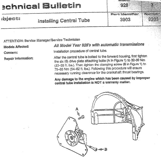
Porsche says that fixing the clamp to 85Nm and after that, fixing the flexplate
to the flywheel will cause pressure on the TBF which is not covered by warranty.
The clamp should be the last to tighten. They are absolutely right. It also
makes it hard to prove that something else caused a TBF as obviously some
mechanic must have screwed up or did not read the service bulletin at all. And
do all mechanics know all the service bulletins? Do we....?
This discussion can go on and on for ages.... I'd fix the problem without
exactly knowing the root cause.
regards
Theo
1992 928gts Midnight Blue (2006-)
1988 928s4 Cherry Red (1999-2006)
The Netherlands
http://jenniskens.livedsl.nl
http://928gts.jenniskens.eu
=======
Johnny,
Agreed, both acceleration and decelleration will cause twisting forces. I
thought it was said differently, like decell would reverse it. Obviously not.
At some point all forces are in balance if you count the friction of the clamp
in too. Yes, friction under the clamp plays an important role here.
The real question is where does that force originate from.
Think of the frictional forces like this: Imagine the clamp not from steel but
from plastic. A plastic clamp on a broomstick. At forces the steel deformes
pretty much. If you twist the plastic clamp with force, and pull out the stick
with a axial force, you will see tiny movements every time you do that. Turning
forward/reverse is a good practice to remove the plastic clamp from a stick. The
clamp moves bit by bit until it is off. Just pulling would not do it.
Did you notice this:
http://jenniskens.livedsl.nl/Technical/Tips/Pics/TT%20clamb%202886.jpg
Look at the movement marks. I did not do this. These are traces of internal
movement under the clamp. The whole thing twists and deforms under load.
Imagine this, please follow the thought:
- we start at zero pre-load
- we drive and for some reason the TT shortens (assume, we know there is a
force), pulls on the clamp
- the flexplate bends to the rear
- we pull harder
- the rotational forces cause micro movements under the clamp, and the TT is
pulled out a 1mm
- the rotational forces stop, and the system goes in rest.
- the clamp does not move but holds since the cause of loosing grip is gone
(rotational)
- the flexplate is now 1mm pushed towards the engine (TT back to normal)
- next time we drive the TT pulls again, but needs to compensate the 1mm preload
- it needs to shorten 1 mm to reach the zero preload point
- TT shortening pull continues and forces reach a point where the clamp slips
again, lets say 1mm extra
- rotational forces stop and the system settles again, but now at a pre-load of
2mm
- the force from the flexplate is less that the friction force that holds the
clamp on the TT
- the flexplate is now bent 2mm into the engine direction. Without rotational
force the clamp holds that position
- and so on. The max movement I heard is about 4mm.
- maybe at some point the the flexplate makes the clamp move back a little until
forces reach a equilibrium, who knows
Imagine shortenening of the TT of lets say 5mm. That seems like extreme to me.
One other option is that the crank itself causes this, basically moving the
flexplate. It would pull the flexplate towards the engine. I don't see that
happen and the crank play is just 0.2mm or so. One more option is the thermal
effects, where the expansion of the tube is different than the expansion of the
central shaft. But 5mm?
So.... So I'm still puzzled. I'm an electronics engineer, mechanical is not my
game.
Anyway, my big concern is that 2 or 4mm pre-load on the flexplate is achieved at
300-500kg force. And this is so much that you can’t expect the flimsy thrust
bearing to cope with it. But worst is that this is not a momentary force, but a
structural one that is at its highest point when the engine is not under load,
and it decreases as the engine is under heavy load. Even reverses direction I
think. The severe load is when the engine is poorly lubricated, just after
starting. That is why all those thrust bearing failures happen. Not because some
lunatic tightens the rear TT clamp, front TT clamp and then starts to bolt down
the tranny by pushing it into position. Same goes for putting in the engine,
causing stress on the flexplate when bolting it down to the flywheel, thus
pulling things together with M10 bolts. Porsche makes it very clear that there
should be a stress-free situation when bolting down the clamp.
In my opinion, and you don't have to agree, it would be best to have either a
sliding clamp at the flexplate, a better flexplate that absorbs the 5mm or....
Or.. a clamp that at least prevents a structural preload when there is no severe
pull from the central shaft. The better clamp makes it a momentary force at a
point when the engine is lubricated at its best (hot thin oil under pressure at
higher rpm's) and settles back at zero pre-load when shut down.
And by far: Porsche said themselves not to have any stress in the central shaft
when tightening the clamp. This preload is what they said *not* to have and
repairs resulting from ignoring the procedure will not be under warranty. So if
you still think it is ok to have flexplate pre-load you must think again :)
Damn long story, I know, it also helps making up my own mind :)
Ok, lets rest his issue until a *new* bright idea pops up.
regards
Theo
1992 928gts Midnight Blue (2006->)
1988 928s4 Cherry Red (1999-2006)
The Netherlands
http://www.jenniskens.eu
http://928gts.jenniskens.eu