In response to Will's request and the
other interest I thought I would start the "detailed write-up" with a little
background, and then will give the blow-by-blow in some "short?" segments. This
first goes like this:
Over the years I have taught myself to work in various mediums and with
different processes. I even gave a weekend "seminar" at my son's engineering
college on processes, particularly the design and fabrication of a monocoque
structure in sheet aluminum for possible use in a utility bike frame. But I
digress.
I began to learn about working in plastic over 20 years ago when I had a need to
form some wing tip light lenses for the CAF torpedo bomber. Since then I have
learned that you can do a lot with sheet plastic, not to mention a little
exposure to plastic injection, which I wont go into here. One thing you can to
is of course buy it thin and form it cold to a very limited extent. Most
forming however is done by heating the plastic to varying degrees above 200F,
and for our purposes here, upward to around 385 if I am remembering correctly
(it might be only 285, but I will have to remember when I start the oven up on
this project).
I learned that you can blow sheet plastic, suck it, as in vacuum forming, and
push it mechanically, as we are going to do in this case, and stretch it over
various other kinds of forms or molds. I made windows for my airplane by
stretching Plexiglas over forms I had made for the shape I needed.
In the hatch latch liner case I am going to use the process of pushing the
plastic through a hole that has the outside shape of the top area using a plug
or mold having the shape of the inside of the part that we need. When I do this
I find that the plastic must be held fairly securely in the machine we are
making so that it will stay in place while the part is being formed.
The machine that I am making is described this way:
It will be a levering devise which is hinged on one end. Overall it is only
about 16 inches long. The main body or frame of the devise will consist of a
small piece of 1/4 inch aluminum plate about 5 by 7 or 8 inches which will have
the female hole in approximately the center. To it will be bolted an end plate
at 90 degrees made out of 1/2 inch aluminum plate about two inches tall and 3
inches wide. On the sides of the base plate will be two alum bars out of 1/2 by
3/4 inch aluminum stock that will bolt along the sides of the machine and will
double as hold down bars for the plastic. They will be connected at their outer
end by a short piece of round bar as a handle.
To the minge plate at the other end (the 1/2 inch plate) two more of the bars
will be bolted loosely so they will hinge. outward on these bars will be bolted
a cross piece of bar stock to which will be mounted the male die that is formed
to the shape of the inside of our finish part. At the other end of these bars
will be another round bar handle, and on this I am making a latch devise so that
I can clip the two sets of handles together when the part is formed. Otherwise
I have to hold them together with clamps while the machine and the plastic cool.
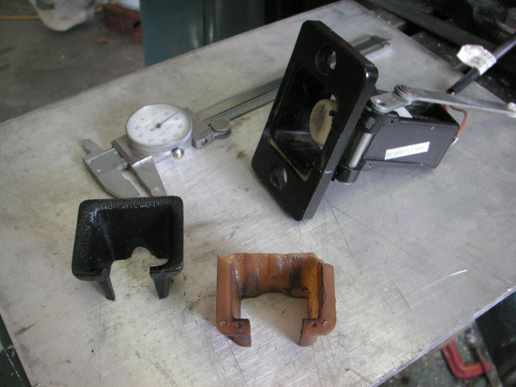
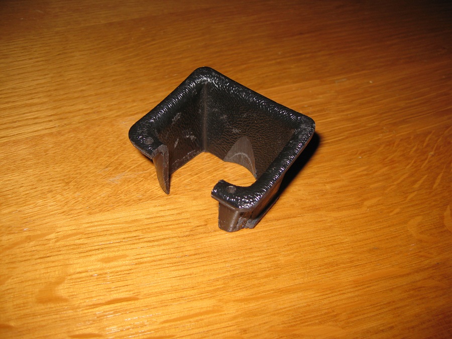
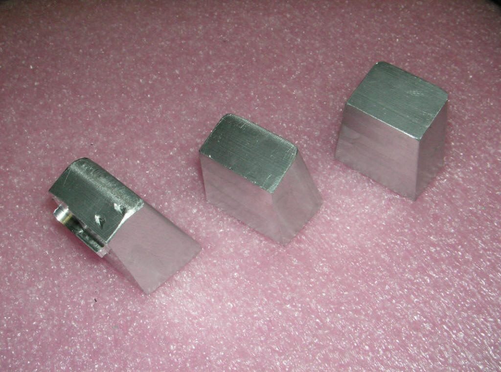
This first picture shows the first three attempts at making the plug or die for the male side of this forming machine.
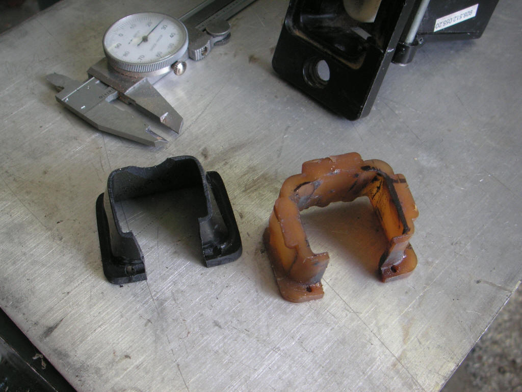
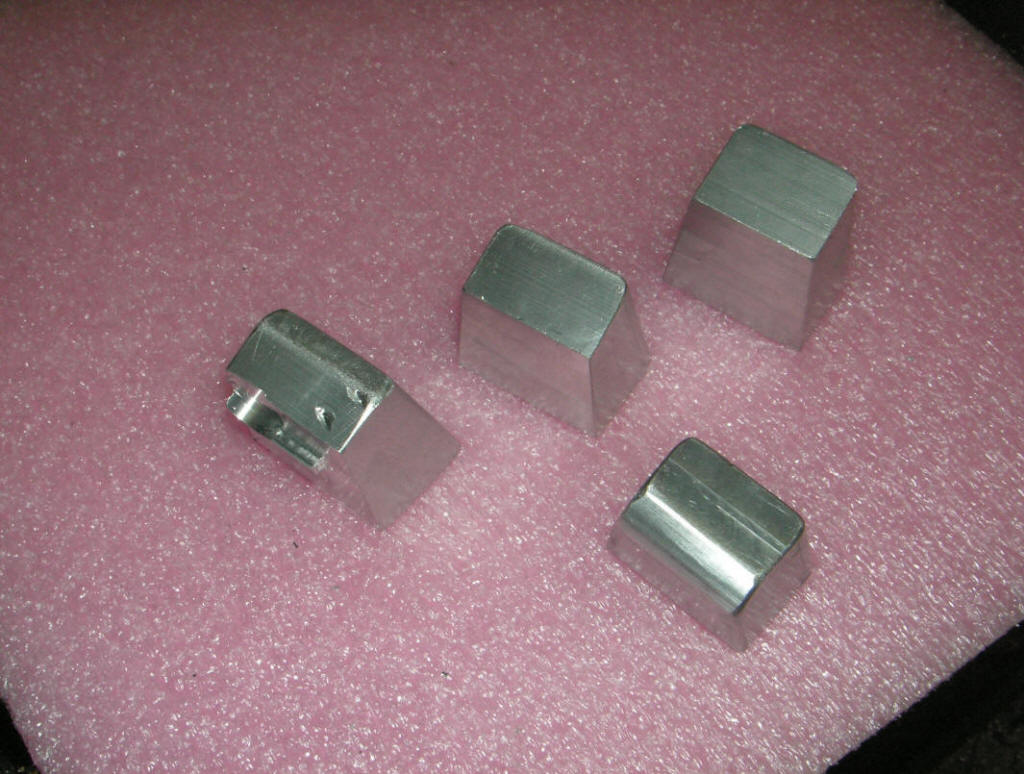
The second picture shows the three first attempts with the final version in front.
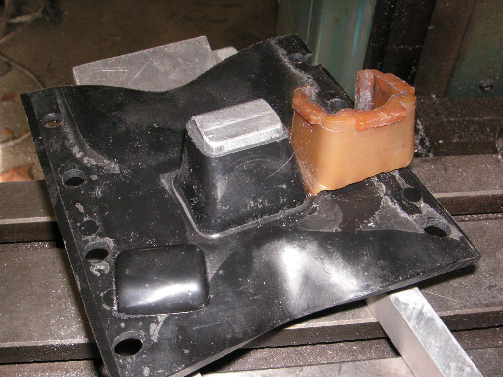
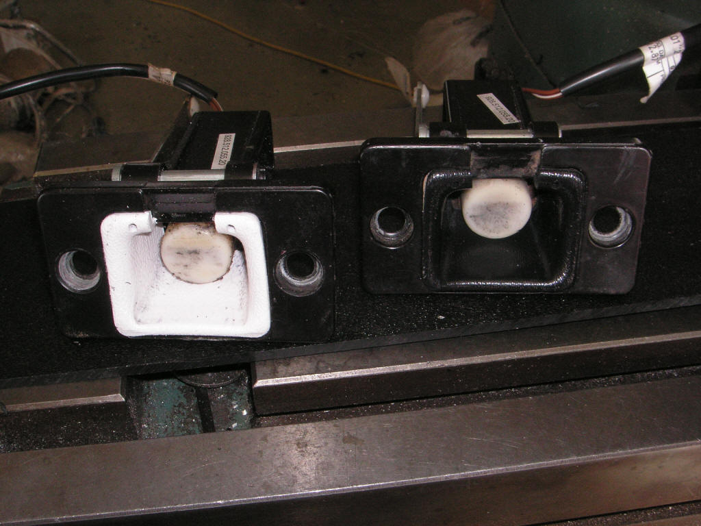
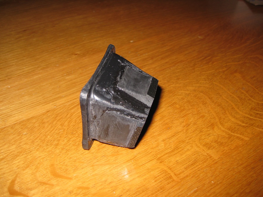
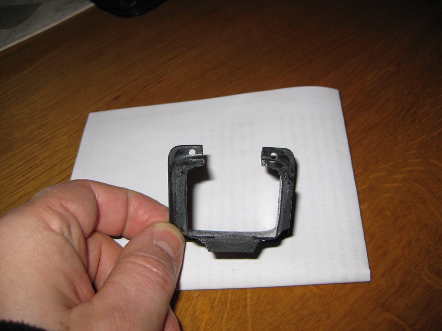
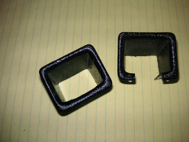
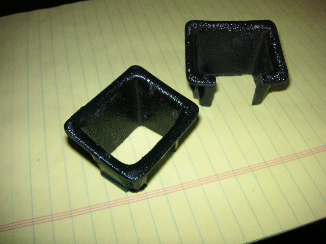
The third picture shows the final die with the remains of the liner I am using for reverse engineering.
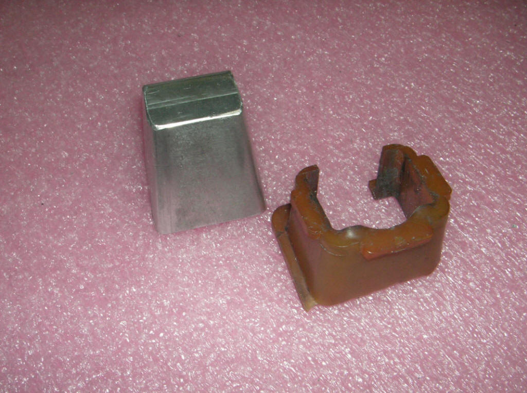
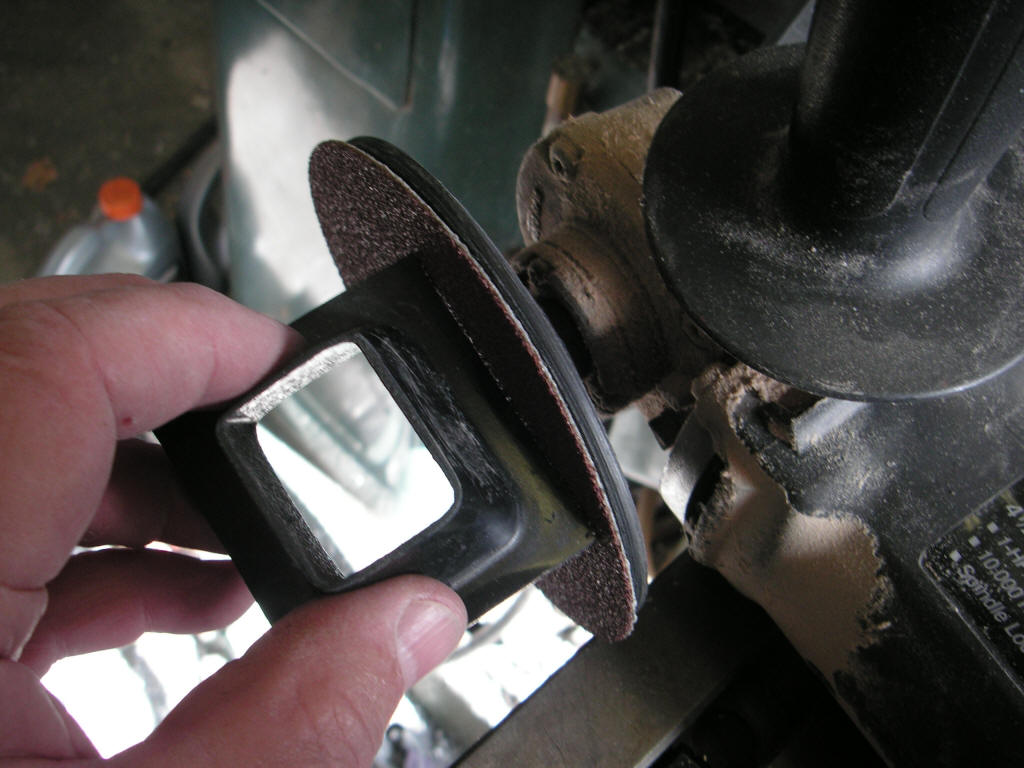
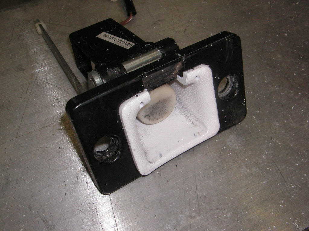
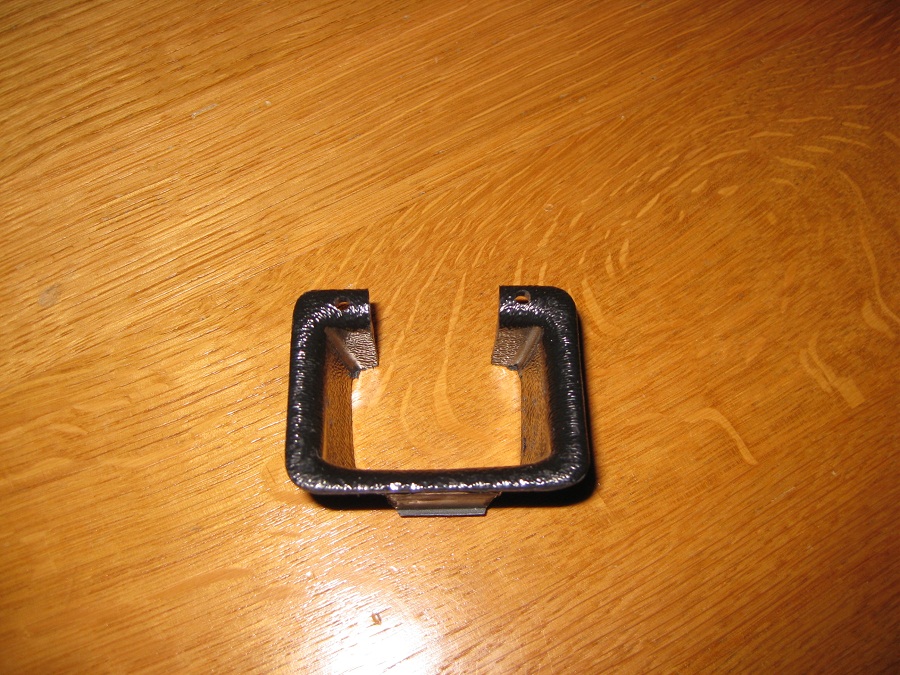
This picture shows the original liner slipped over the new male die.
The fifth picture shows the end plate
that I have described where the upper part of the machine hinges.
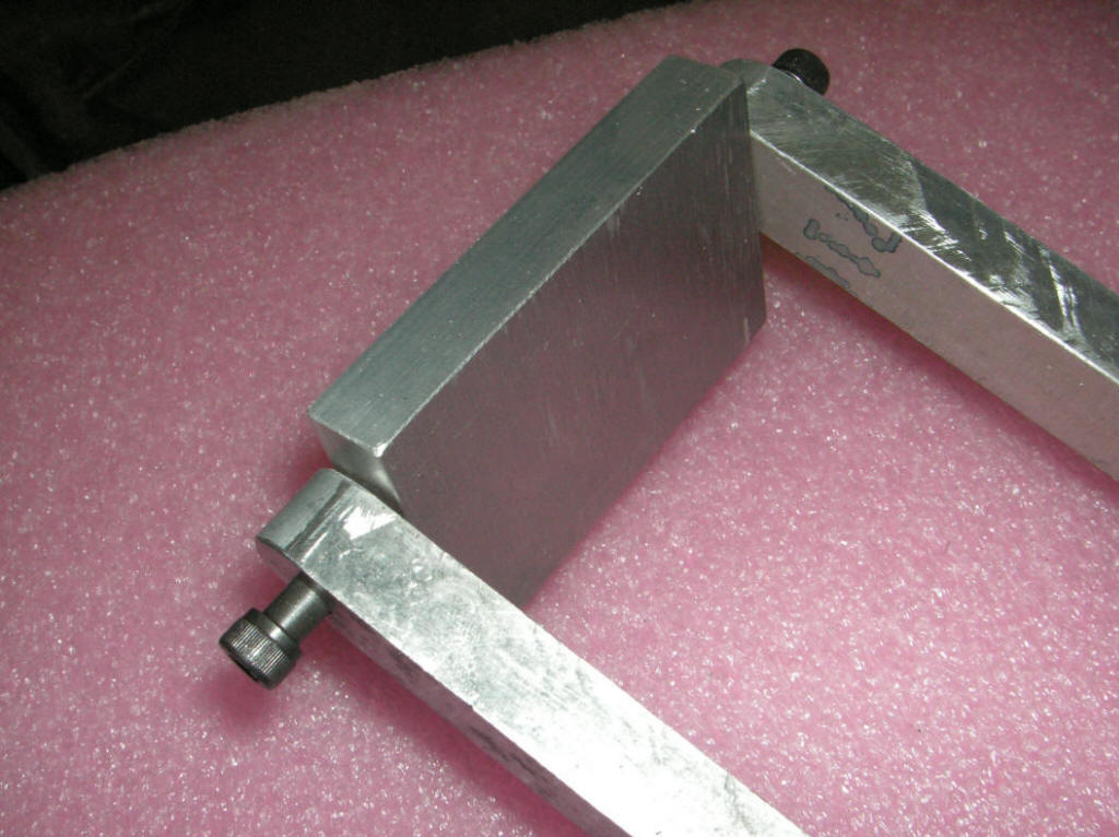
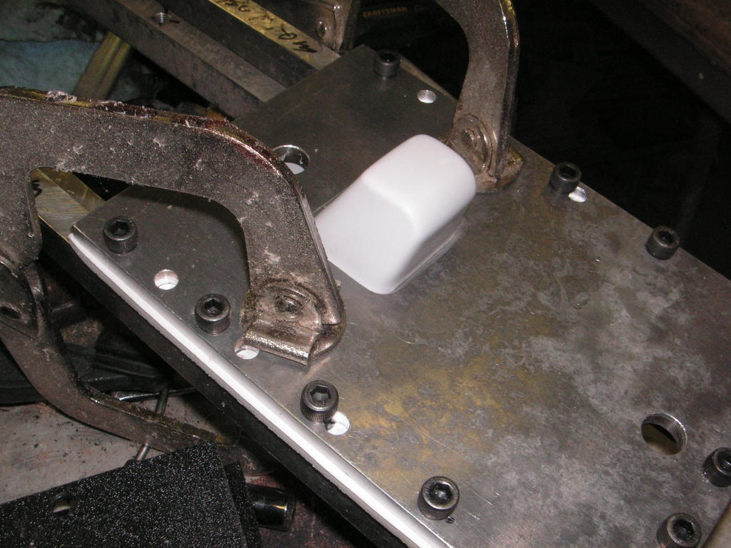
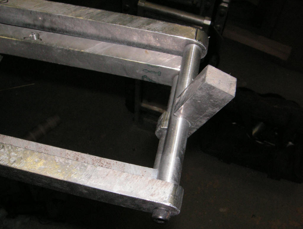
This picture shows the handle end of the upper lever part of the machine with the little floppy piece that I am going to make into a latch to hold the machine together while the whole thing cools.
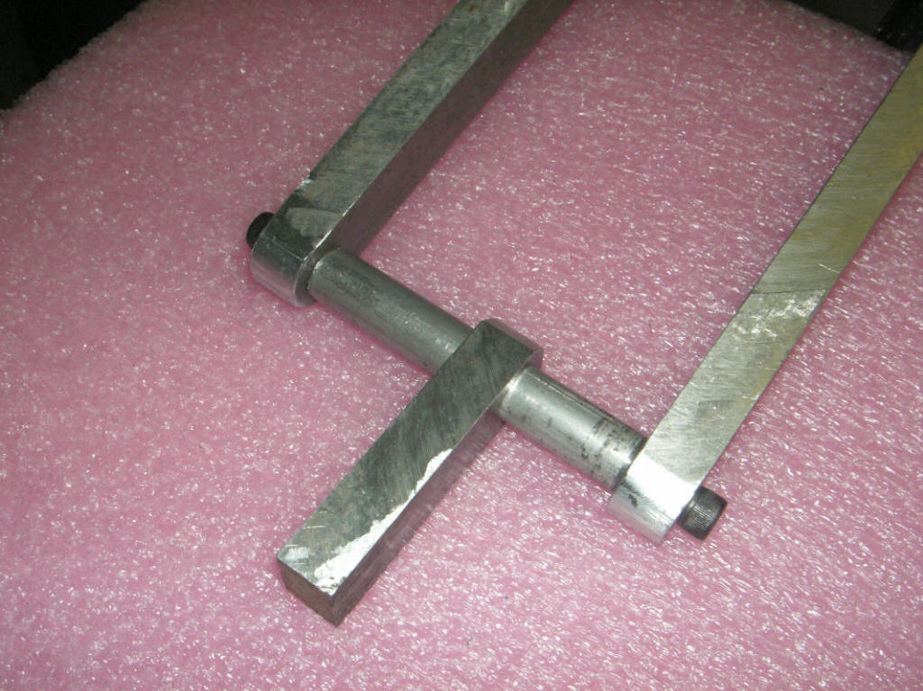
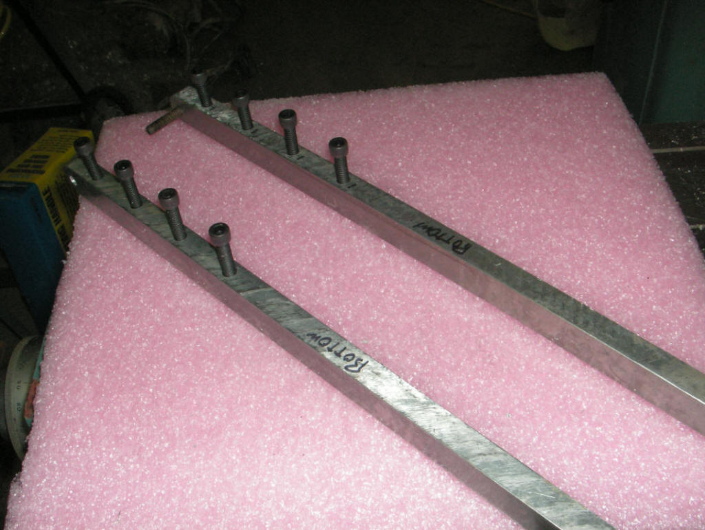
This second picture shows the two handle parts of the bottom which will double as the plastic hold down bars.
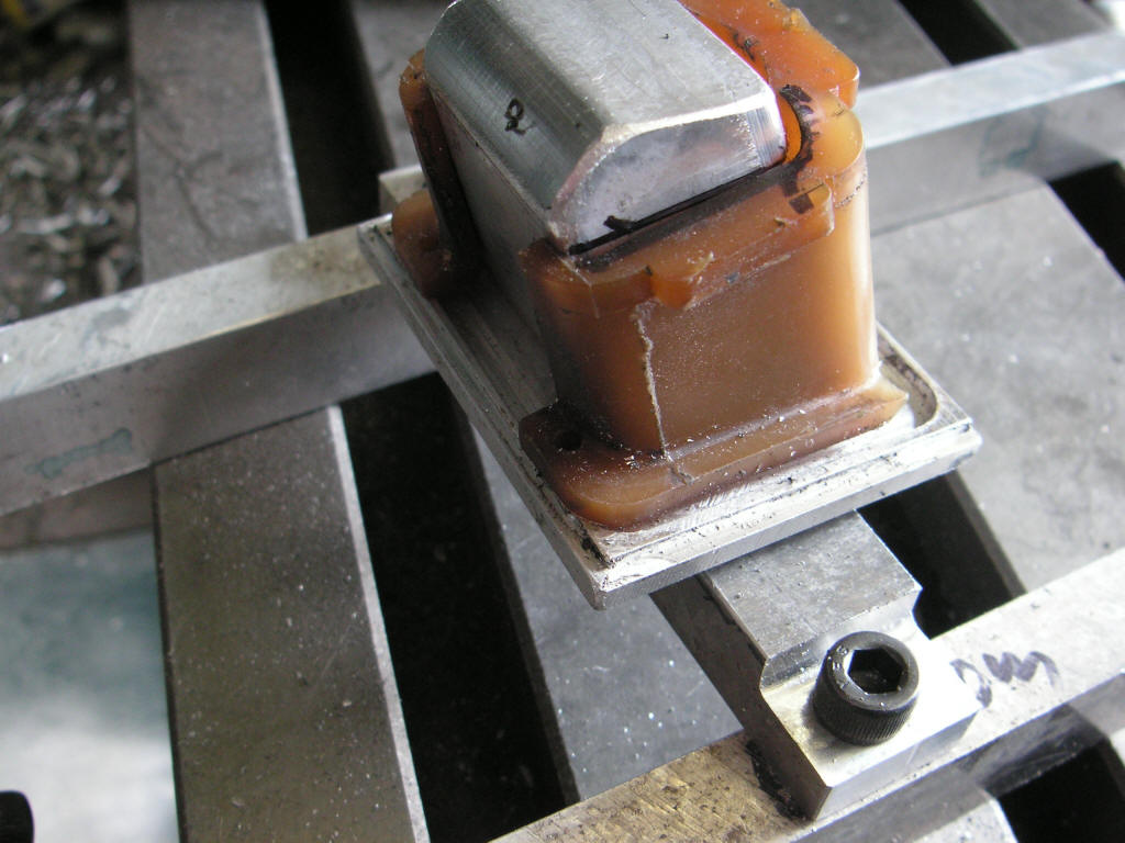
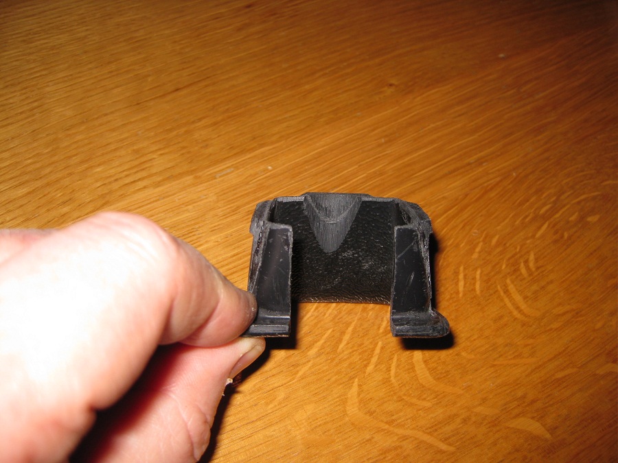
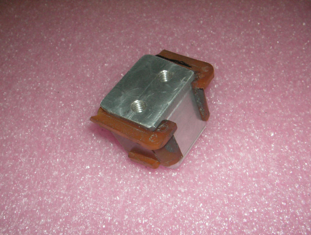
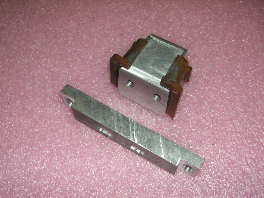
This picture shows the male die together with the short cross member that it mounts to.
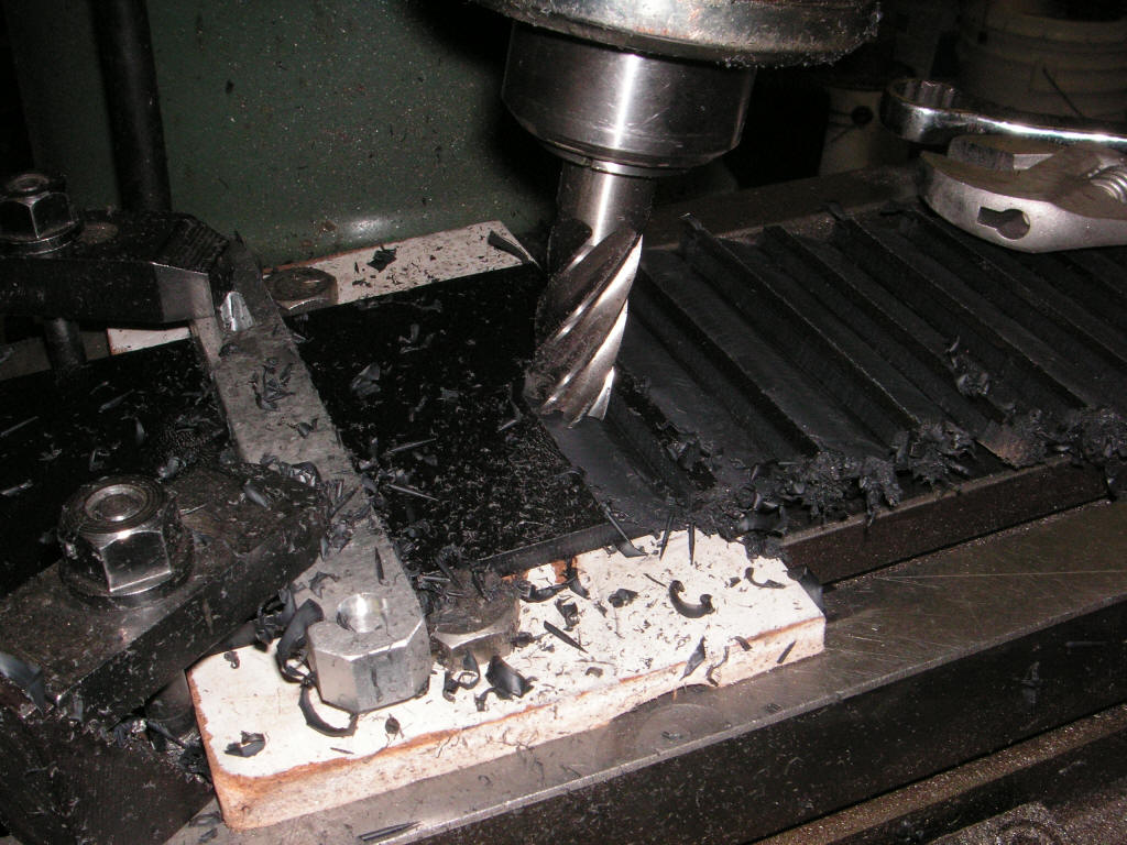
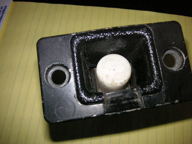
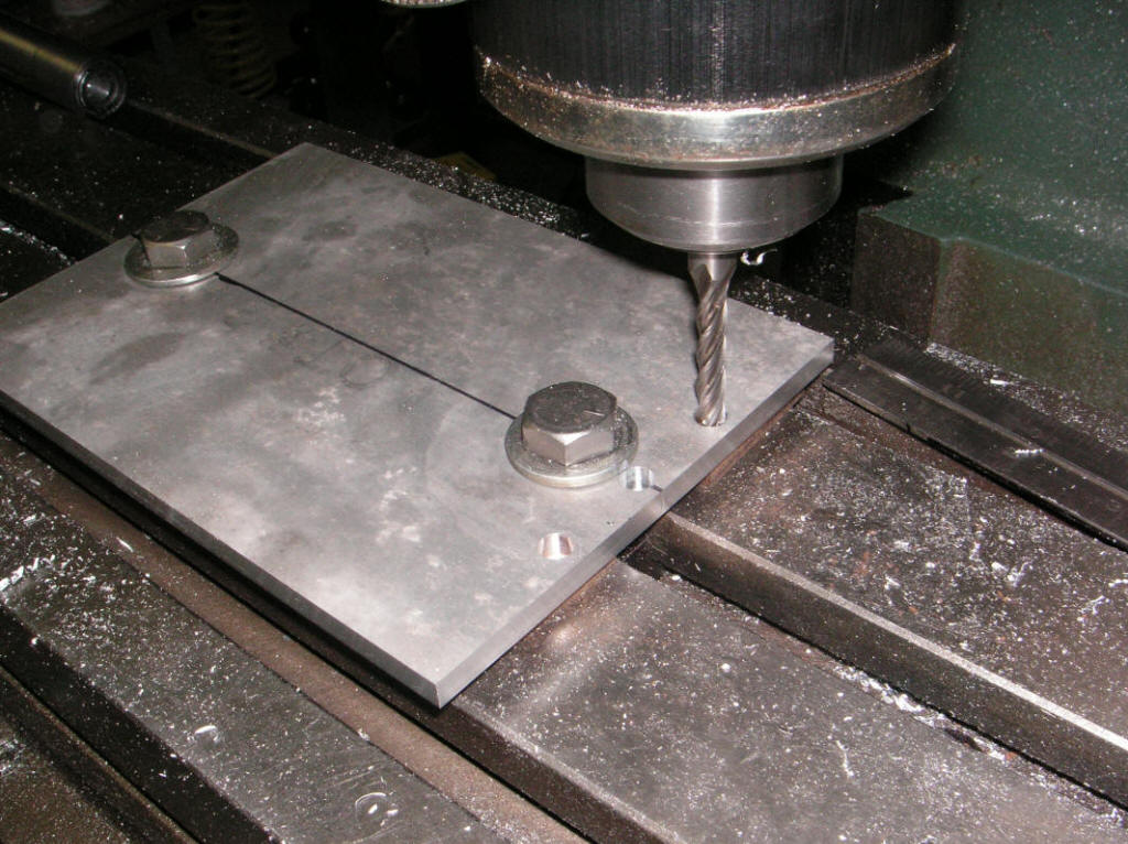
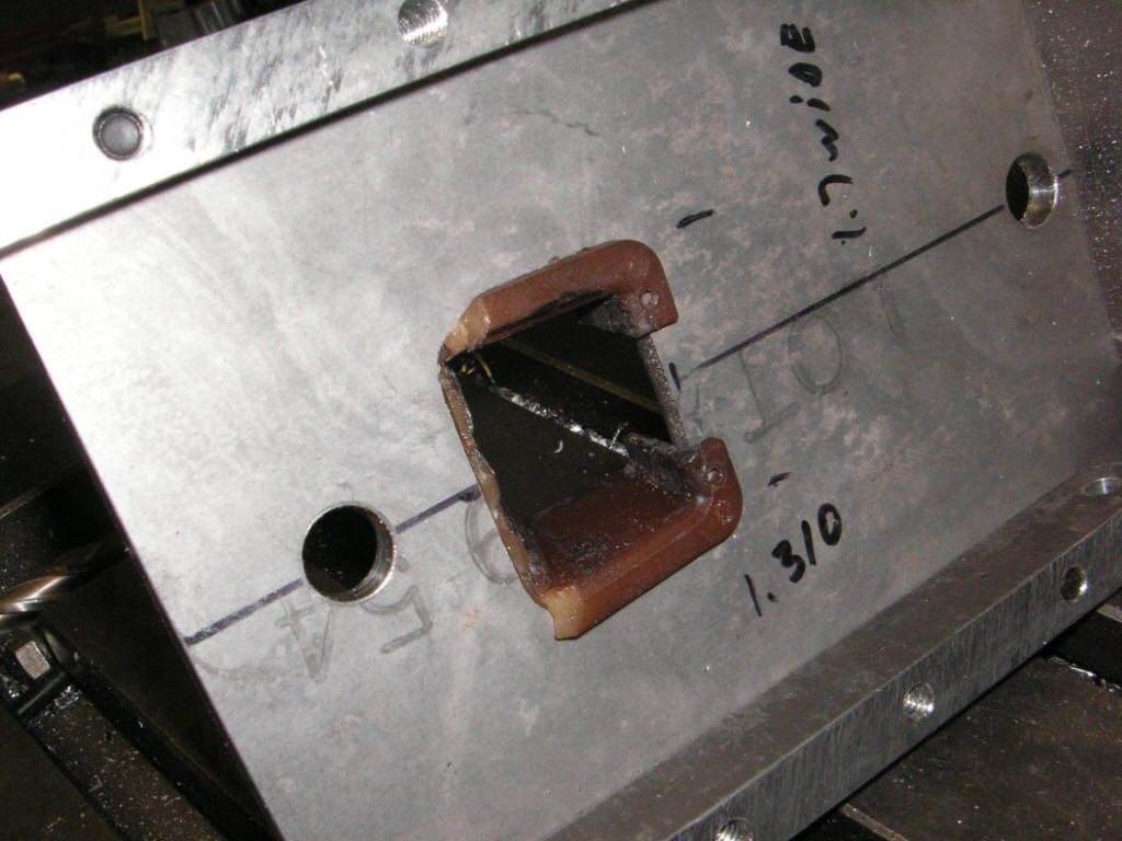
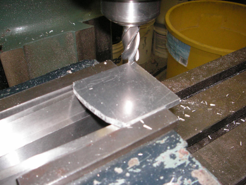
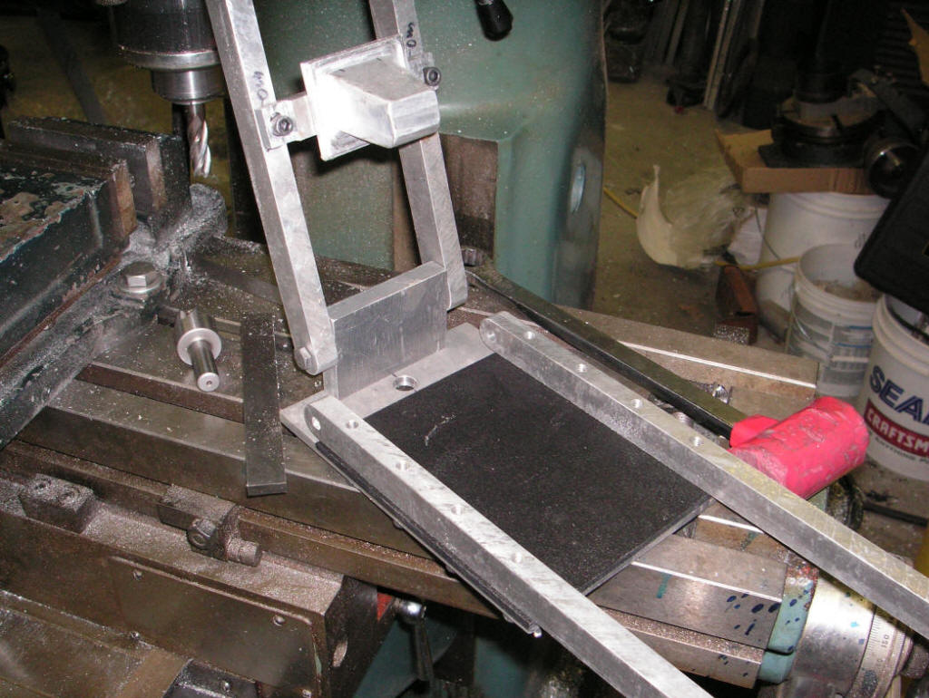
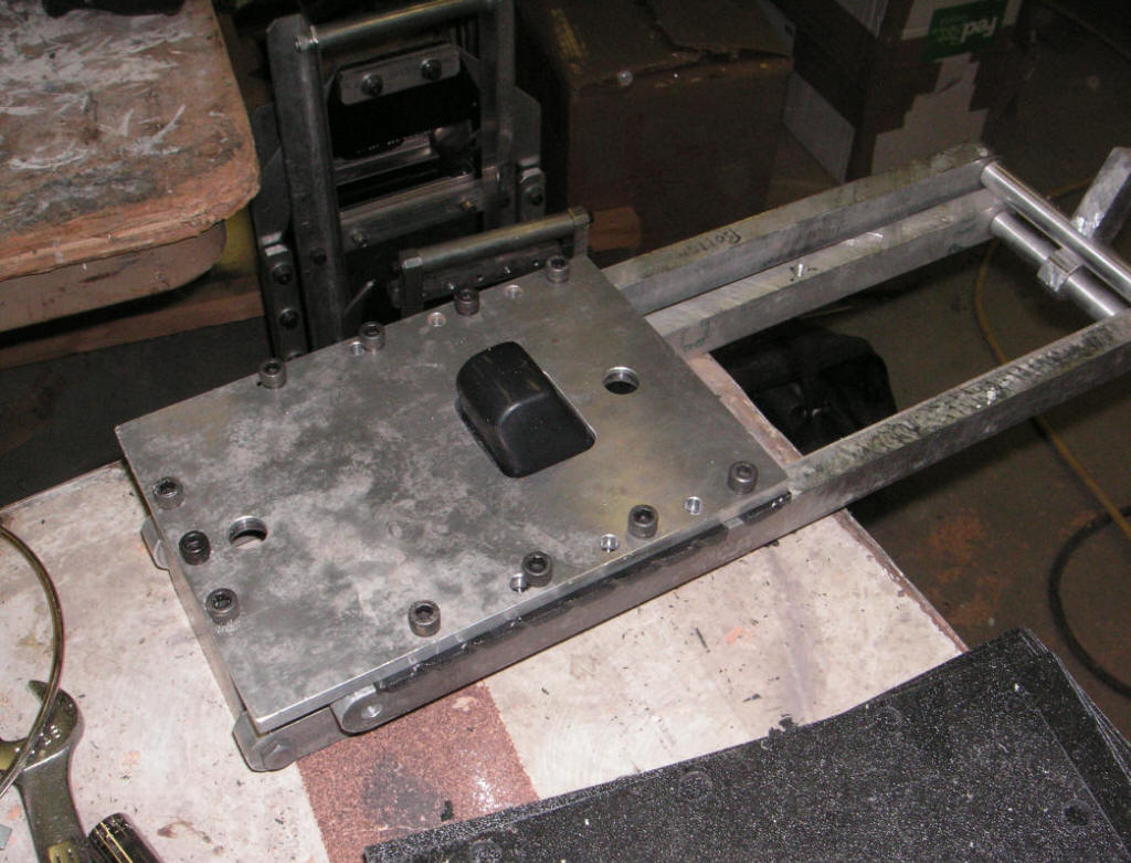
Here I am starting on the base plate which will also become the female die for the bottom of the machine.
Here I have completed the base plate/female die in the mill including some extra holes I made by mistake.

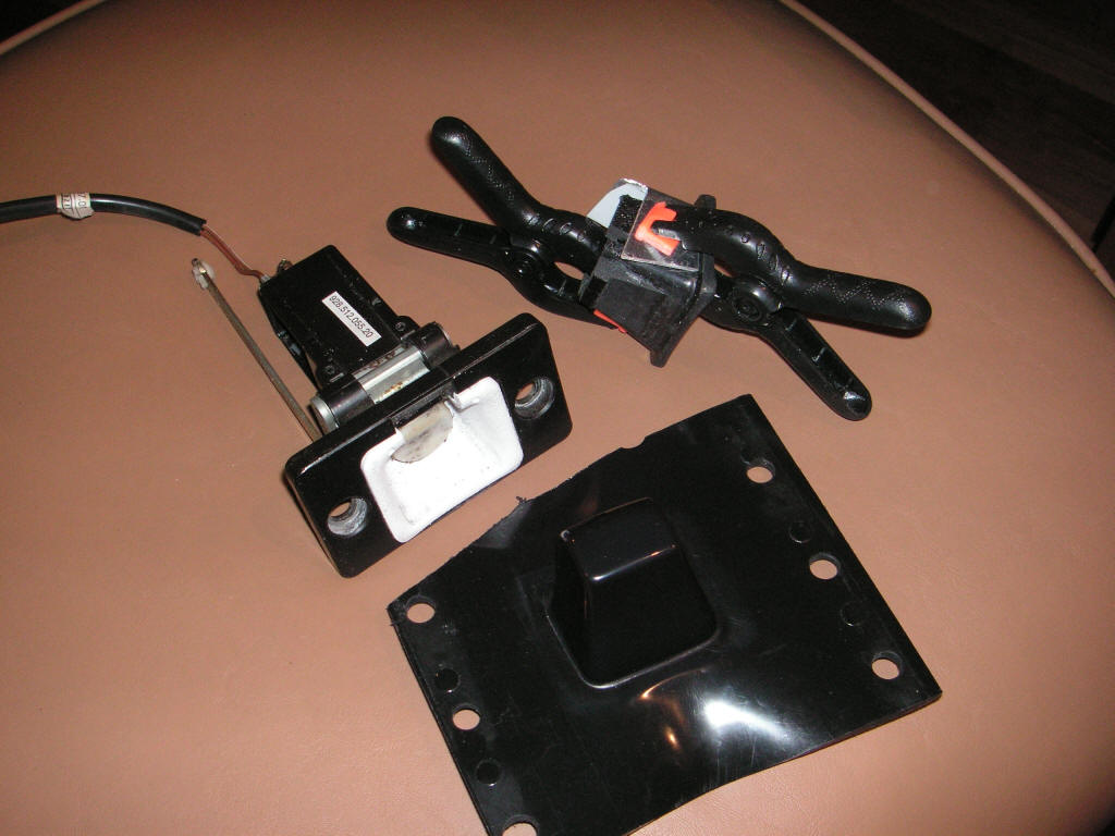
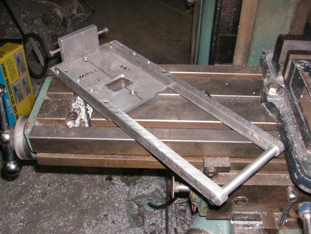
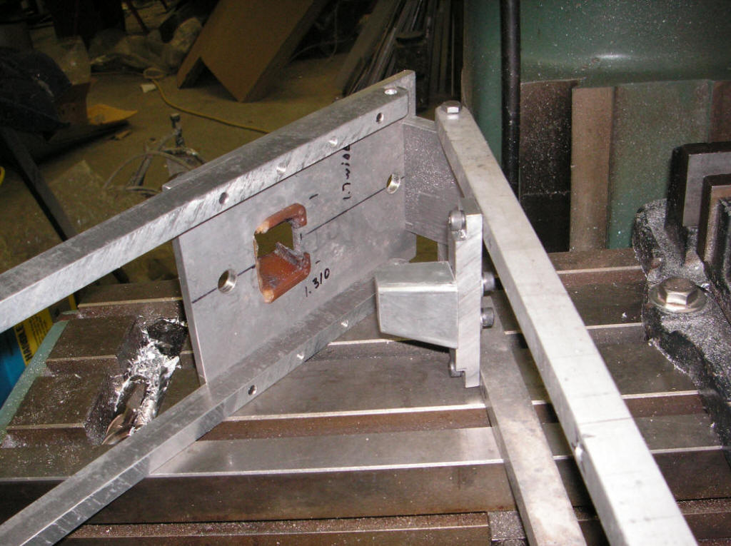
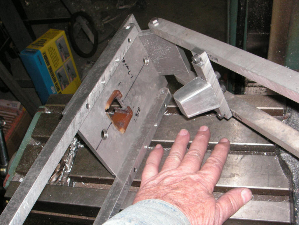
These pictures show the first assembly
attempt of the machine. they are in sequence, I think. The last picture has my
hand in it for perspective.
Here are some of my other thoughts on
this latch liner I am trying to make:
If you haven't figured out by now you will soon be able to get the true picture
which will show that my approach to this item and its fabrication is somewhat
primitive. I am not making a part that, if it succeeds at all, will look
much like the original. As I suggested in one of my previous lists about this
project, I am not making anything like an injection mold which could
be made to cast an exact duplicate of the original factory item. And, that may
be what has been done by others.
What I am trying to make is a suitable substitute for the liner--somewhere
between the injection mold approach and the idea of just putting a piece
of plastic in the latch receiver to hold the latch prong fore ward. My
part, if successful, will work much like the original, but it will be black
(although I have and can get some white ABS plastic sheet if there is any
desire or need for a white part rather than black. I think my part will
function just as well as the original and may even last much longer-only time
will tell on that.
However, my part is going to look somewhat crude when viewed by itself. For one
thing the basic body of the part is going to be stretched fairly thin, maybe
down to about a 16th of an inch on its sides. The factory part is roughly twice
that thick. The other thing that you will notice with my liner is that the body
that I am going to try to form in this little machine I am making is not going
to have the locking tabs on three sides of the bottom as with the factory item.
What I plan to do is mill some plastic of the same ilk into wedge like pieces
that will have the locking tabs along one edge and then simply glue them, or
maybe only just one of them, to the sides of the liner. That is one of the
things that is going to make my part look kind of crude. However, one nice
thing about ABS is that when you glue it you use glue that is just the same
plastic dissolved in a solvent so that when you put it on the parts it dissolves
the parts a little, then when the solvent evaporates what is left is two pieces
that are he same as if they had always been together as one.
Next I want to go into some of the things I will be doing with the actual
forming part of this project. Later.
Jerry Feather
----------
I just came in from the shop and found
that the temperature is 285. I found the part at 284 and the plastic was soft
and rubbery, so I took it out and formed it. It did not tear and seems to have
formed just about right. There is some chance that it has a thin spot
around the bottom which probably means that I need the drop the temp to about
275. I'll try that tomorrow.
In the meantime I have the machine out on the deck railing cooling so I can
take it apart and see what kind of adjustments I might need to make besides the
temp. I took a few more pictures this evening of this progress so when I get the
thing apart and take a couple more I am going to send them to you and Theo, if I
don't have a hitch. Last night I had a time trying to figure out how to get my
computer to read the SD card.
Didn't Theo do a great job with the spot he put on his web site? I think it's
super.
Jerry Feather
S4's (6)
-----------
I finished the forming machine this
evening and then put it to the test. It works just fine and only needs a couple
of adjustments. One is, I think, a reduction in the temperature and the other is
a shim under the male die so that it forms a little deeper in order to get the
strike off around the top by the little plate I made tonight. it is barely
touching now, but looks like when it is adjusted it will do just what I was
hoping.
I find that at the 285 temperature it is a little too soft and made the button
of the liner body stretch out too thin. When I have had that happen in the past
I have cured it by working the part a little cooler.
Here are some pictures if you want to
add them to your web site and make another link or add them to the last link,
whatever.
This first picture is the beginning stages of the little plate that goes above
the male die to strike off a line around the top surface of the liner.
This second picture show me placing the male die on the plate for measurements.
Here in the third picture I have done some of the machining of the recess that will leave the little rim around that will strike of the top surface of the liner.
Here in the fourth picture we have the
plate mounted with the male die in the machine.
Picture five shows the plastic work piece in the machine ready to go to the oven.
Here is part two
This first picture of part 2 shows another view of the assembled machine with
plastic ready to go.
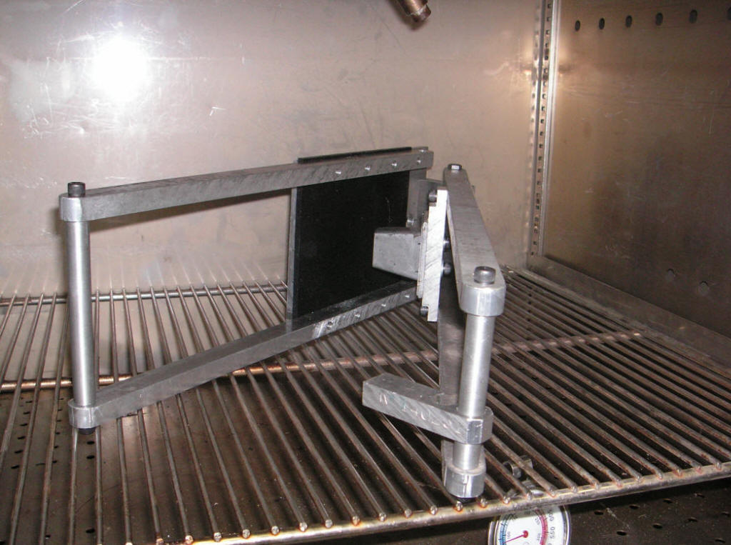
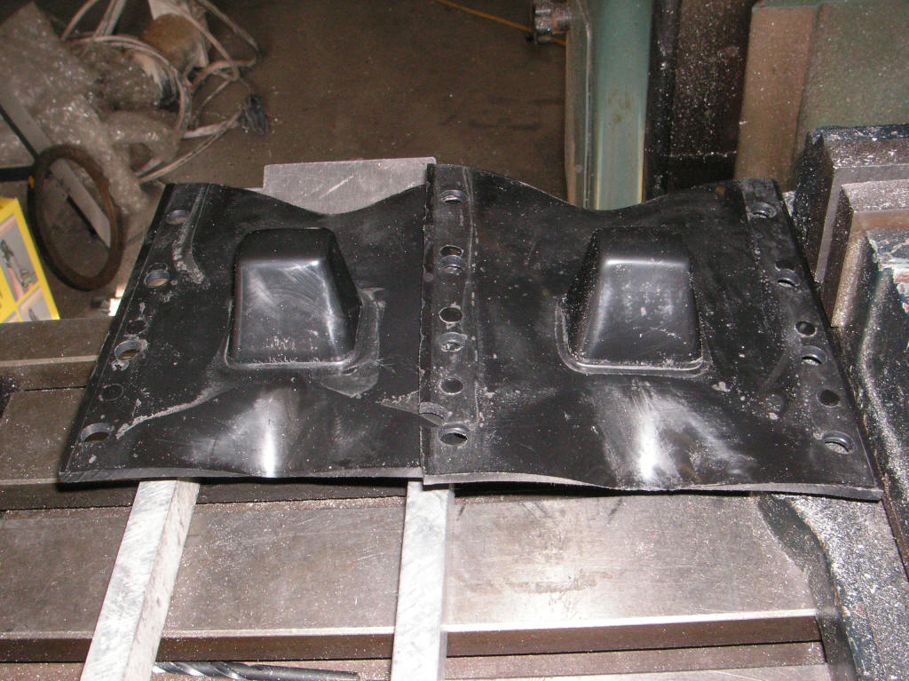
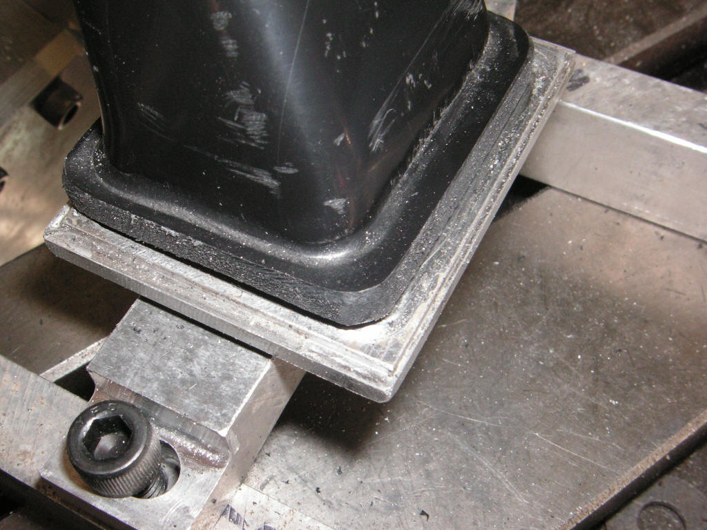
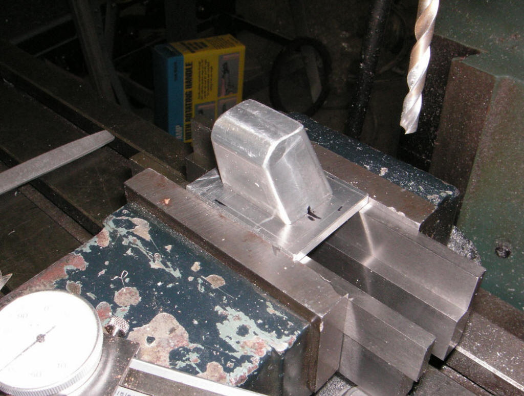
Here is a picture of another design of
forming machine I made a while back to form part of the new design of 928 center
console glovebox that is deeper that the original cassette box and tougher. This
machine is a double forming machine since it first forms the outside of the
glovebox body and then it is heated up again and forms part of the inside--a
flange that the finished inside compartment is riveted to after the body is
covered in leather. There is a completely formed glovebox body still in the
machine.
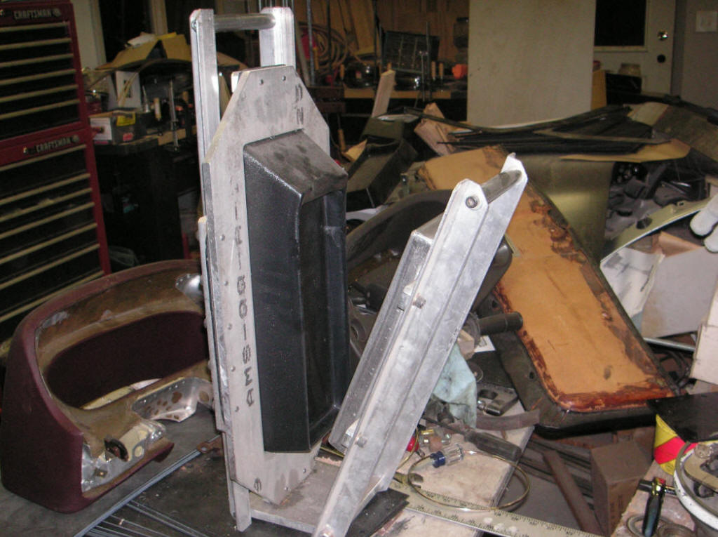
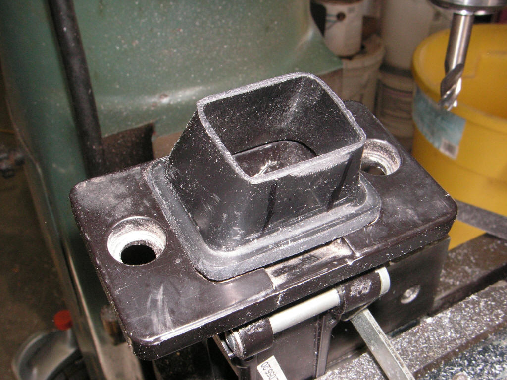
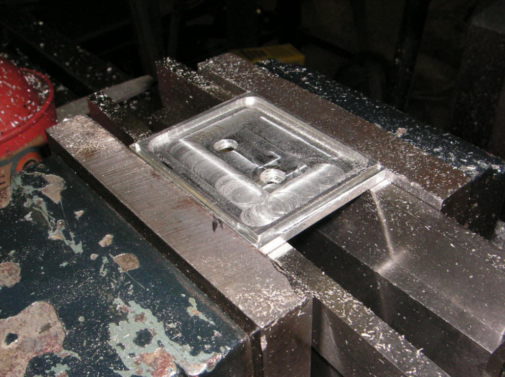
This machine is also for the glove box project and it forms the lid liner for the new glove box. There are two other machines--one for the inside box compartment and one for the lid outside.
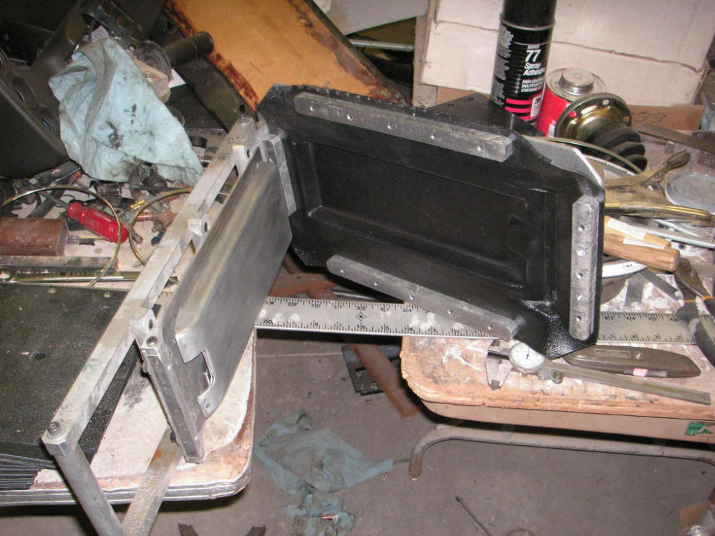
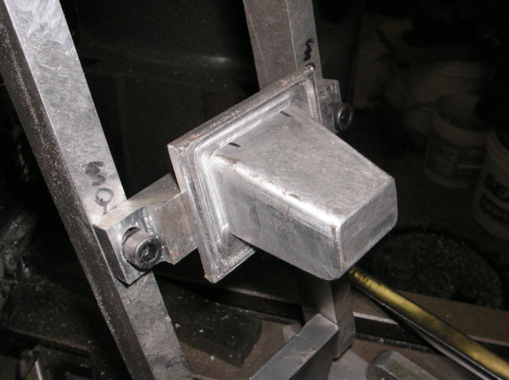
Four, part 2 shows the machine after the part has been formed.
Five shows the handle end of the machine and how the little latch works that I had to do last.
By the way, one of the above pictures shows the machine fully loaded and in the oven, but now I can't tell which one it is; or maybe I left it out.
Part three.
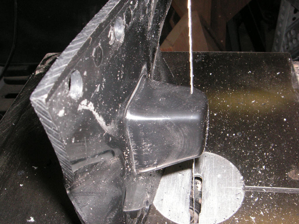
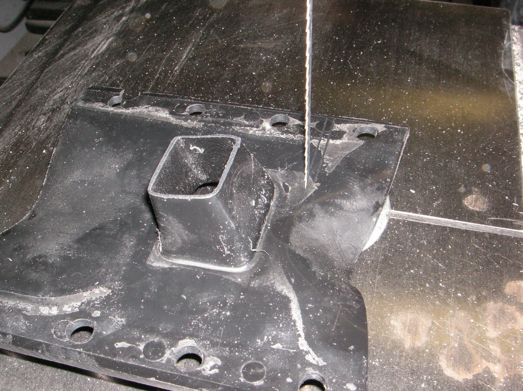
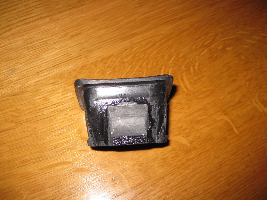
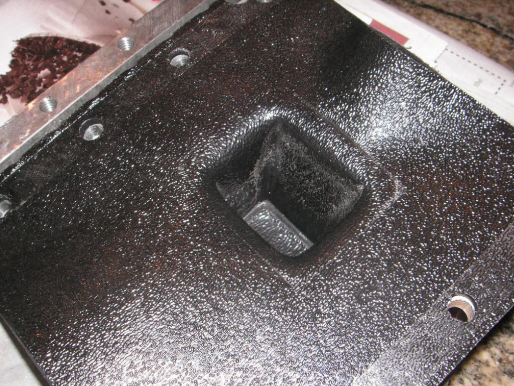
First picture P3 shows the top view of the formed part while it is still in the
machine after the male die has been pulled out.
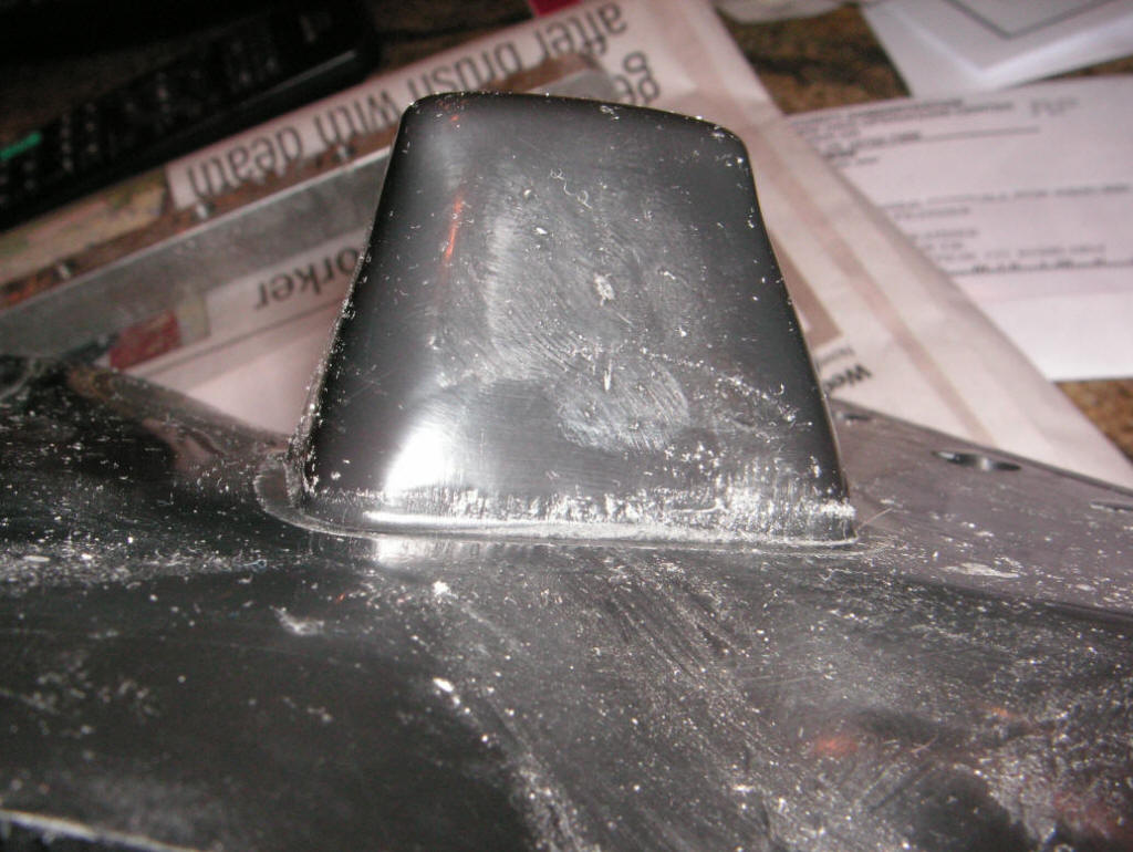
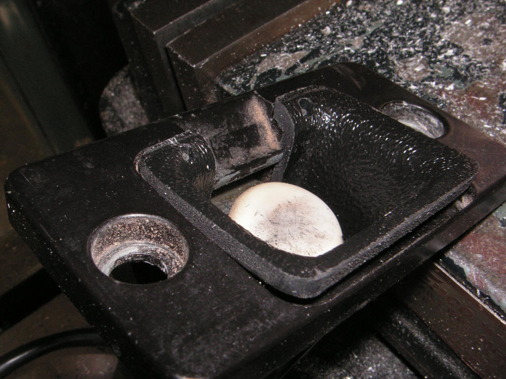
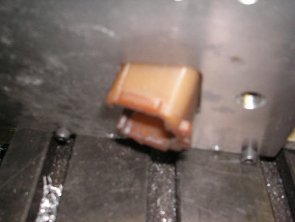
Two P3 is a close up of the part formed.
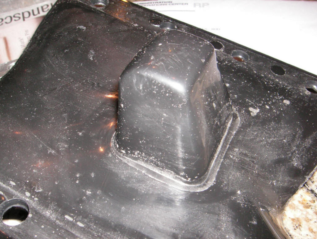
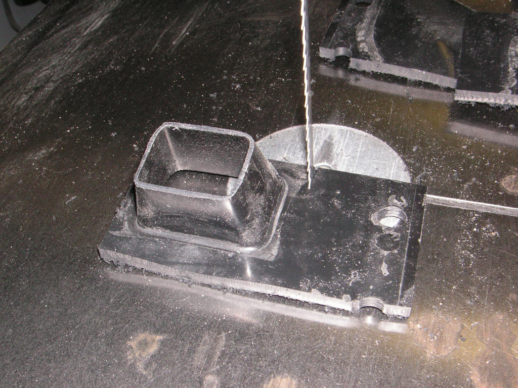
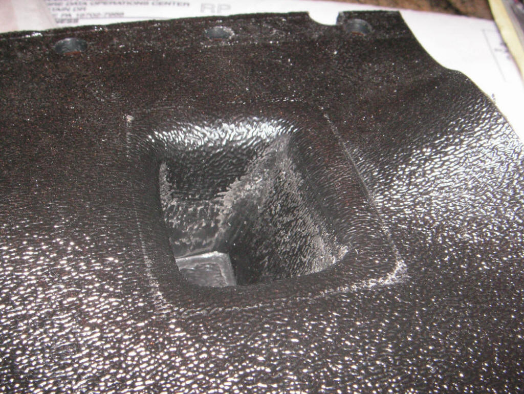
Three P3 is another close up of the part from the other side.
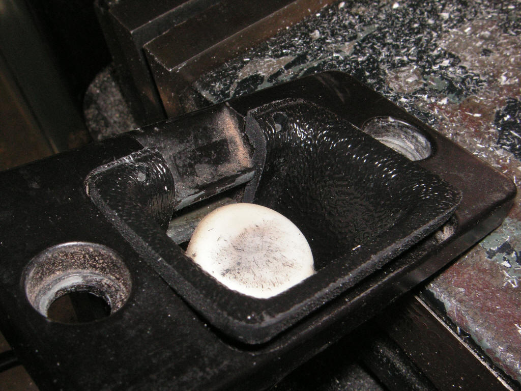
Four and five are about the same but one may not be quite in focus--I can't tell from the tiny thumbnails I am selecting from. They show the broad side of the part and if you look closely you can see the cresent-like line near the bottom which is the line where the plastic was at the edge of the hole before the forming push was made. It shows how much plastic was pulled into the hole to help make the part rather than using what plastic was just covering the hole. Neat Huh?