Very good instructions are here: Upper A-Arm Poly Bushings (was this from 928motorsports or 928intl? Dunno where I got it from)
Upper A arm Bushings
Replacement
--------------------------------------------------------------------------------
I have acquired or should say rescued a 1986.5 Iris blue Automatic. She needed
a lot of love and my wife said I needed a project. I am replacing the upper
rubber in the A arm bushing. The originals were trashed from age. I've read
different things but can't seem to get the same answers from all the different
posts so I will try to explain what I have come up against..
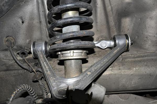
1. Got the front end disassembled and replacing multiple items.. bearings, tie
rods, lower ball joints, brakes rebuilt, brake hoses, etc.
2. Inspected the A arms, replacing upper boot, ball joint ok and tight,
repacking.
3. A arm removed and tried to press out the bushing. Bushing seemed impossible
to remove but it came out with a lot of work and force. (it was in multiple
pieces.) I used a press with supports to drive the rubber out. All is left is a
metal sleeve that remained behind after cleaning the remaining rubber out.
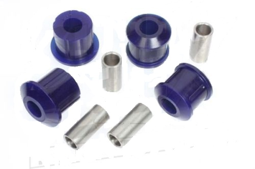
4. Poly bushings (928 motorsports) were going to be the replacements but when
pressed back in they seem like they will not allow the a arm support rod to fit
correctly. They make the space between the two bushing too short and when
pressed in fully the support rod stops are forced into the bushing 1/4 to 1/2
inch.
Here are my questions.
A. Does the metal sleeve need to be removed leaving just the bare aluminum?
B. Is there a difference in the clearances between the a arm bushing "eyes"
between 1985 1987 (mine is that weird year 1986.5 . A arms changed size and the
upper ball joint was not repairable anymore.) I know the overall distance from
the back of the a arm to the front changed, but what about inside between the
bushings. The service manual shows that but nothing more.
C. Is there a difference in the bushing between those years? Any specs on
tolerances to help match up what I need.
D. Are the poly bushings going to cause trouble later and should I just go back
to the OEM bushings? I all ready have the poly ones.
E. What is the distance between the a arm bushing "eyes", inside to inside
length for a 1986.5 model. Could I have possibly tweaked the a arm inward since
the bushing were so hard to remove. I thought I had it supported but it was
really tough to get them out. The two A arms are the same inside length minus a
few millimeters and still seem square when measured out..
Any help would be welcomed
=======
A...... yes use a hack saw and cut a slice in the metal sleeve.
Take the blade off the handle fit it through the open A arm hole and then refit
it to the handle and carefully cut the sleeve
B...... the bushing should be the same
C....the poly bushings should fit tighter and reduce the amount of flex in the
mounts
D.. you could try matching the A arms to each other for a measurement
__________________
MrMerlin
=======
Quote:
Originally Posted by lesman2001
A. Does the metal sleeve need to be removed leaving just the bare aluminum?
If you mean the steel sleeve that was the outside of the original rubber
bushing, Yes it needs to be removed. New PU bushing don't have one by design.
Quote:
B. Is there a difference in the clearances between the a arm bushing "eyes"
between 1985 1987 (mine is that weird year 1986.5 . A arms changed size and the
upper ball joint was not repairable anymore.) I know the overall distance from
the back of the a arm to the front changed, but what about inside between the
bushings. The service manual shows that but nothing more.
You can't tell from PET as the upper A arms are only listed as a compete unit
including the steel bar that fastens them to the body.
Quote:
C. Is there a difference in the bushing between those years? Any specs on
tolerances to help match up what I need.
See Steve (Sendarius) comments below - earlier ones seem to be smaller diameter.
Internal diameter of A arm hole for the bushing on a 90 or 88 is 44mm dia.
Quote:
D. Are the poly bushings going to cause trouble later and should I just go back
to the OEM bushings? I all ready have the poly ones.
Once installed correctly they should be OK but see my comments below.
Quote:
E. What is the distance between the a arm bushing "eyes", inside to inside
length for a 1986.5 model. Could I have possibly tweaked the a arm inward since
the bushing were so hard to remove. I thought I had it supported but it was
really tough to get them out. The two A arms are the same inside length minus a
few millimeters and still seem square when measured out..
I'll measure an installed Arm shortly (need top get wheels off) - 9 1/4" between
inside faces of the ears.
Other comments
If you installed the PU bushings with the original outer steel part of the
rubber bushings still inside the Alu A arm (Pretty bloody hard work) the PU
bushing will get squeezed inwards too much and become lengthened.
The supplied washers (the pair between the bushings and the steel bar that
fastens to the body) are in my opinion too small an outer diameter, after a 1000
miles or so the washers start to work their way into the bushing. I refitted my
upper A arms with one Stainless steel fender washer with an OD of approx 50mm
(2")
and on the other end a turned down SS fender washer with an OD of 43.5mm so it
will go through the ear of the A arm. (Edit this may only apply to S4+)
__________________
Jon in OZ
Rennlist Member
928OC Member
Black SE
Slate Grey '90 GT (hers)
Ex UK, Ex NZ (me and the 928s)
=====
I used the Dremel for the inner sleeve.

__________________
Robert, 1994 GTS midnightblue, the Netherlands
========
I used a torch and press.
__________________
Landseer
======
Quote:
Originally Posted by tlsmith1999
Do you remove the inner steel rings for both the OEM bushings and the after
market Poly ones?
If you mean the crush tube - yes the new poly bushings should come with a new
crush tube that you press into the centre of the poly bushing after the bushing
has been pressed into the A arm.
Crush tube is bonded to internal bore of the oem rubber bushing and is a loose
fit in the internal bore of an uninstalled poly bushing. Called a "crush" tube
because when you tighten the retaining nut the tube gets clamped between the
Nut/washer and the shoulder on the bracket.
__________________
Jon in OZ
========
I would like to thank everyone for all the help and tips. I did have to remove
the metal sleeves that were left behind and that was a feat unto itself to say
the least. Once I got the procedure down it didn't take long to get the other 3
out. I am going to try to attach pictures since I'm sure someone else will have
the same questions and I would like to give them a hand.
First I would like to answer a few comments. I would like thank you for the
measurements on the inner eye to eye. I did not damage the a arm, mine is 9 1/4
also and still measures square. As for the getting the bushings into the eye
with the metal sleeve not being removed.. with a 12 ton press, you can get just
about anything through a hole, may not fit right as I found out, but it will go.
A big hammer is great but with a 12 ton press you can really foul things up.. On
removing the sleeve by cutting it, I just not sure where the steel would end and
the aluminum begins. I can't see giving the a arm any cuts of any depth by
accident. A lot of stress rides on these, literally..
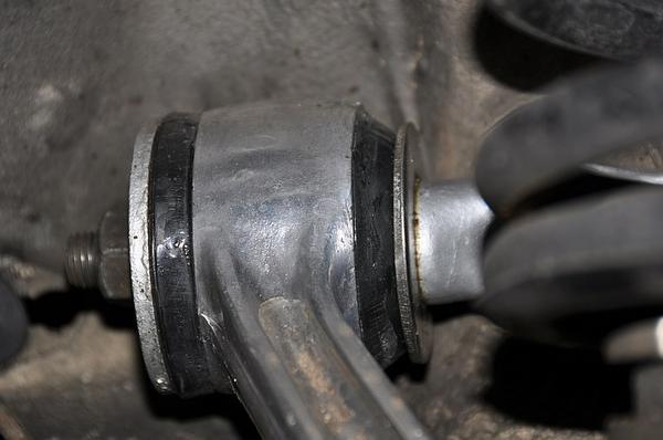
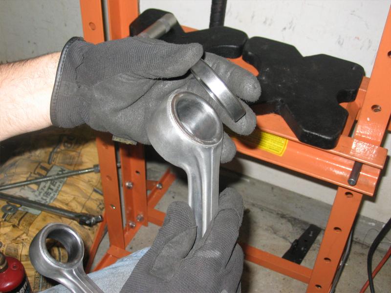
1. Just in case someone does not know what the metal sleeve I was discussing is,
here is a picture. I had problems finding a support that allowed enough grip on
the a arm eye to support it but allow the metal lip to slip out of the eye. Tip
: Here is another reason to keep those old parts around. The inner bearing race
from the front wheel is just the right size using the large end with the tapper
toward the metal sleeve lip. You can see the metal sleeve on the face of the
eye. This is the sleeve that has to come out. The bearing race fits exactly over
that lip and allows for you to start the removal.
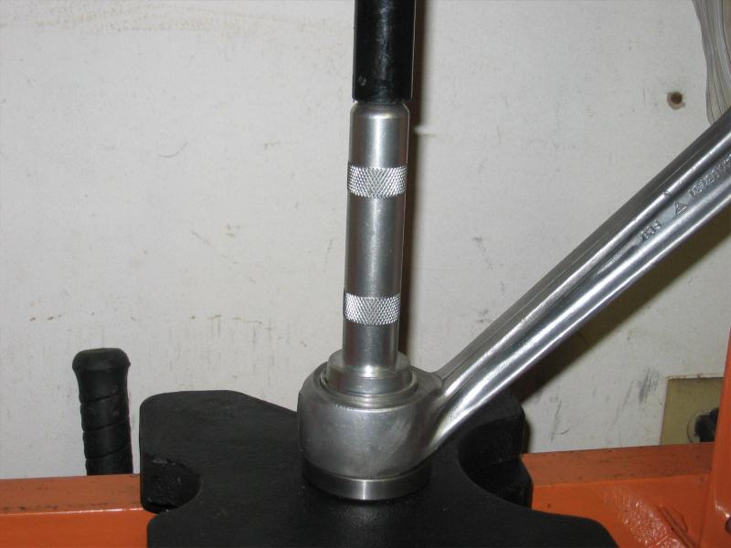
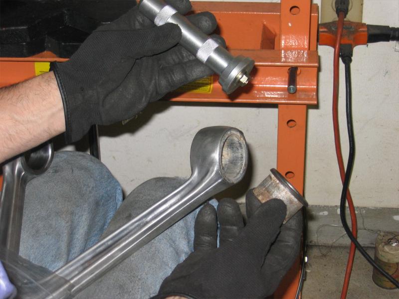
2. A great tool from Harbour Freight. Tool number W83020. It is a bearing race
and seal drive and its cheap. One of the drivers fit exactly in the eye with
play and its aluminum (other year models may be different but they have other
sizes in the kit). You can see the driver in the press and placed in the eye.
Use the flat side that is for seals. Another picture shows the tool better. It
fits and will not scar up the inner face. Make sure you press square on the
tool.
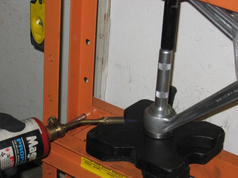
3. After 20 some odd years, the metal to aluminum bond scoffed at 12 tons of
pressure. I had to apply heat to the eye, not a lot, but got it good and warm.
The resulting pop will make you think you broke something but that means its
just started to move. Keep apply more pressure at that point. It should keep
popping and moving. The very last metal sleeve came out with no heat so this may
vary. Either way the sleeve will come loose with pressure, if you use heat, keep
the flame moving.
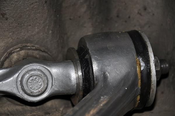
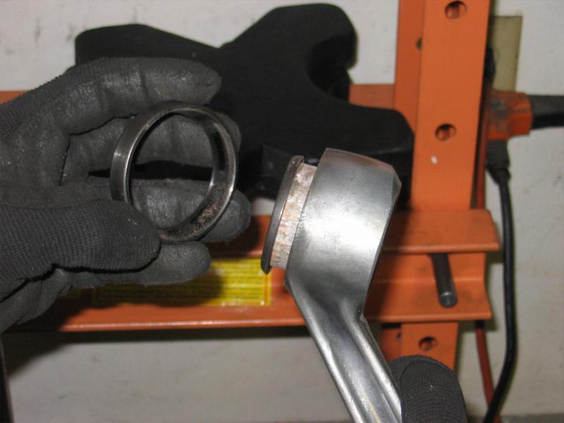
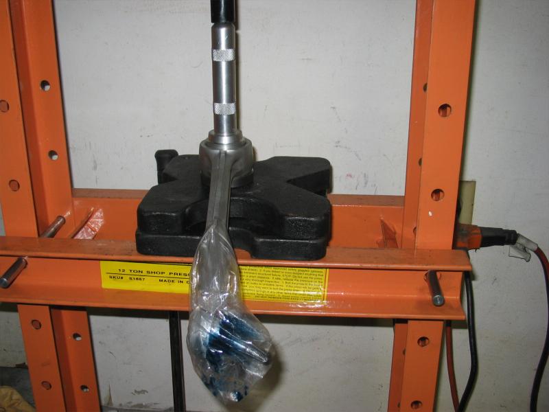
4. This picture shows the metal sleeve after it moved with a resounding pop and
I pressed the metal sleeve all the way to the end of the bearing support and
plate. The metal lip was curled up due to the tapper of the bearing face as it
pressed toward the end. The metal sleeve will not press all the way out using
the bearing but now I found a different deeper support that fit better to the
eye since the diameter of the lip was reduce greatly and the support could get
more of the face of the eye. Just applied pressure again and it will creep out.
On one I had to reapply heat to start it moving again.
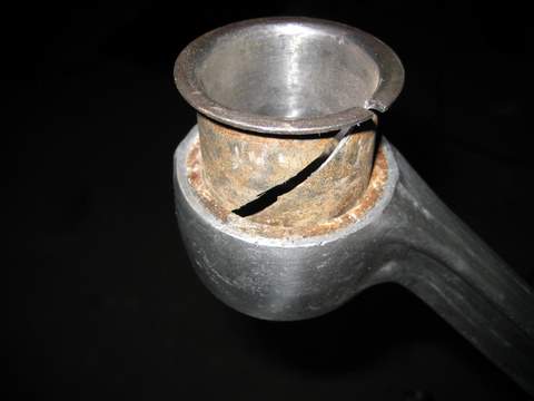
5. Picture of the tool, the metal sleeve removed and the a arm. The corrosion
that fell out was amazing. A new understanding of di-electirc properties and
effects on metals. And who said science class wasn't interesting.
6. The other side of a arm and sleeve being removed. On the first side the press
had enough clearance and length for the ram to fit through the upper eye to the
lower. You can see this in the first pics. The only problem on this side is
clearance due to the angle of the eye and arm . I had to use multiple plates
staggered to give the angle enough clearance. The bag is to keep the ball joints
clean that I repacked.
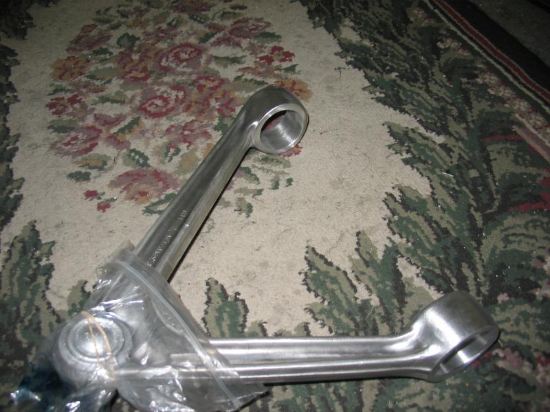
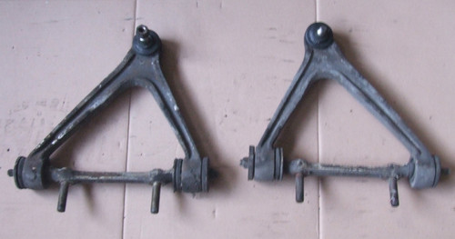
7. Here is the finished a arm. Factory fresh looking. A little fine wire
brushing and cleaning of the inner eye and its ready for the bushing to be press
in. I have no doubt that the poly bushing will fit correctly now that everything
is prepped right. I have destroyed the first bushings by pressing them back out
and now I await the new ones to arrive the next coupe of days. A not so cheap
lesson but beats the cost of a new or used a arm.
thanks again.. I hope this helps someone else who runs up against this problem.
The bearing direction in step 1 is incorrect. Sorry about that. The bearing
tapper is away from the sleeve lip. In other words, the larger tapper opening is
placed on the eye with the smaller tapper end away from the eye. Anyone who
tries this would see the proper direction, but I hate getting those replies.."
you got the bearing direction wrong". So I'll be that guy..
Lesman2001
-----
Alternative product:
 PU bussen A-arm.pdf
====
A question about the nuts that attach the A-arm to the bracket that holds it to the chasses (where it pivots): The nuts are M12x1.5 this is a fine thread type, not the normal M12 which is 1.75 pitch.
regards
theo