- slacken and partially remove the timing belt
- retime the cams
Here is a list of all the parts you will need to get, with quantity in parentheses:
(13) 928 104 115 02 ....... rubber donut seal for valve cover bolts
(1) 999 701 693 40 ........ o-ring for variocam actuator poking through valve cover
(1) 944 104 463 02 ........ gasket for variocam actuator poking through valve cover
(1) 928 104 447 09 ........ valve cover gasket
(4) 928 104 443 08 ........ spark plug hole sealing rings
(2) 900 123 050 30 ........ crush washers for variocam oil tube
(1) 999 701 844 40 ........ o-ring for variocam oil tube
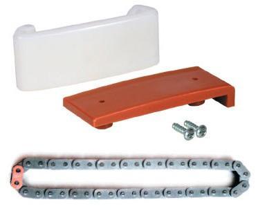
(1) 944 105 501 05 ........ cam chain
(2) 944 105 509 00 ........ cam tensioner pads
(1) 900 117 073 00 ........ woodruff key for exhaust cam
(1) 999 510 022 08 ........ main cheesehead bolt for cam sprocket
(1) 999 113 282 40 ........ exhaust cam seal
(1) 928 105 215 00......... seal cap at front of head
(20) 999 510 029 02 ....... m8x40 cheesehead cam carrier bolts (I bought 20 m8x40 stainless steel allen bolts from a local specialty fastener store, with 20 washers)
(1) Some Loctite 574
Here is a list of special tools you will need before beginning:
- 8mm cheesehead (triple square) tool
- 12mm cheesehead (triple square) tool
- 27mm offset wrench (you can get away with a plain 27mm wrench)
- large vice, or C-clamp
- three M5x15 bolts
Porsche Specific Tools (recommended, but can proceed without):
- 9248 Cam Saddles
- 9530 Assembly tools for Variocam tensioner and timing belt tensioner
- 9206/1 Flywheel lock (highly recommended)
If at any point you come across a fastener you have difficulty with, don't
go straight for brute force. Try a little penetrating oil, and try the "bolt
wake-up" technique, where you use a hammer and drift to smack the head of
the bolt, in order to break the seizure. Never bang a hammer on the end of a
wrench for this job. If you need more strength, use a pipe or cheater bar
for more leverage.
You will need to undo the timing belt from the camshaft sprocket. It is not
necessary to do a complete R&R of the belt - you can just slip the belt off
of the cam sprocket and slip it back on later. See the Workshop Manual or
Clark's Garage for the full belt replacement procedures. A complete belt job
will also entail a whole new list of parts you'll need.
1. You must depressurize your fuel rail before beginning. Take out your fuel
pump fuse (or your DME relay) and try to start your car. It will probably
start for a moment, then shut off. Crank it a few more times, and this will
deplete most of the fuel that was in the rail.
*Another way to depressurize is to let it sit for at least 1 hour.
2. Disconnect the battery negative terminal.
3. If equipped, remove the front and rear plastic engine bay covers, and the
plastic belly pan.
4. Remove the entire airbox assembly by disconnecting the 4 10mm bolts on
the side of the cross member, the 2 clasps that hold the MAF to the airbox
and the front 10mm bolt holding the airbox to the body. By removing these
connections, you can pull the entire airbox as a complete unit.
5. Set the engine to TDC on cylinder 1. You can use the mark on the cam
sprocket and line it up against the mark on the rear sprocket cover, or for
more accuracy, you can use the mark on the forward surface of the flywheel
(on the "back" of the flywheel, seen from under the engine, looking from the
front of the car toward the back of the car).
6. Remove the starter, leaving it connected, and tie it out of the way. Lock
the engine at TDC using the flywheel lock 9206/1. It is recommended to
install a flywheel lock once you have your engine at TDC, but can be done
without it if you're careful not to move the crankshaft.
7. Disconnect the coil wire from the distributor cap.
8. Using a screwdriver or socket wrench, undo the 3 captive screws holding
on the distributor cap.
9. Pull the cap away and lay it somewhere, with the plug wires still
attached.
10. Undo the 3 captive allen head bolts holding on the distributor rotor,
and remove the rotor. The bolts will stay in the rotor. Don't lose the 3
little aluminum spacers.
Note: If you will NOT be setting the cam timing, and wish to preserve your
current cam timing, you must now put 3 spare bolts (M5x15) and washers into
the holes where the distributor rotor bolts go. These bolts will lock the
cam sprocket's orientation, and preserve your current timing.
11. Remove the power steering belt by loosening the 2 lock nuts on the
turnbuckle and turning the turnbuckle to loosen the belt.
12. Remove the alternator belt the same way you removed the power steering
belt.
13. Remove the 9 10mm bolts on the timing belt cover, and remove the cover
(both parts together).
14. Undo the 3 10mm bolts on the metal cam sprocket cover, and use a
screwdriver to gently it pry off.
15. If you didn't use a flywheel lock, you must do this step. Place a wood
block on the passenger fender inner channel (where all the fender bolts
are), and put a large crescent wrench on the hexagonal washer which is right
in front of the cam sprocket, positioning the crescent wrench so it is as
close to the wood blocks as possible, and stack up some more wood if you
need to. The idea is the wood blocks will push against the wrench for you.
This hexagonal washer allows you to counter-hold the cam while you undo that
big cheesehead bolt in the center. It is OK if you move the cam a few
degrees either way.
*You can also put the crescent wrench on the cam itself - there are
hexagonal sections for this - you need to pop off the valve cover to see
them.
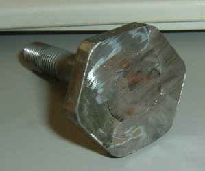
16. Using a 12mm cheesehead tool, no extensions, and either a breaker bar or
a socket wrench with a pipe, undo the main cam cheesehead bolt. Be sure to
hold the tool as straight as possible. If the bolt strips, which it often
does, you will have to grind the head away. The torque spec on this bolt is
48-52 ftlb.
17. Loosen the nut on the balance shaft belt tensioner, release the tension,
and move the top-right portion of the belt down and away.
18. Remove the two 13mm nuts retaining the hydraulic belt tensioner.
19. Remove the circlip on the base of the timing belt tensioning lever.
20. Pivot the hydraulic tensioner so it points more towards the engine,
while pulling the tensioner lever away from the engine. Once the hydraulic
tensioner's piston clears the lever, there will be no more pressure on the
lever. Now you can work the lever off the engine. The lever's pulley has a
lip on the back side, so you'll have to get some slack on the belt to get it
past the lip.
*Another way: take out the timing belt idler roller, and put the bolt back
in with a spacer on it. Use a hook-shaped pry bar to pry between the spacer
and the tensioner lever. Do this enough to slip the belt off the cam gear.
It will take muscle and two people (one to wrestle the pry bar, one to slip
the belt off). This way the lever can stay on.
21. Remove the hydraulic tensioner.
22. Finally, slip the timing belt off from the cam sprocket.
23. Tuck the belt away somewhere, and don't kink it. Use zip-ties, bungee
cord, etc if you need to.
24. Pull off the cam sprocket, zinc-plated shield, and the propeller-shaped
hall effect inducer, all as 1 piece. A little penetrating oil helps loosen
things. Spray some PB Blaster or such around the cam hole.
25. Unplug the Hall sensor. The plastic on the connector gets brittle over
time so be very genle or else the connector will crumble into pieces. It
costs over $100 to replace.
26. Remove the rear metal cam sprocket cover. (3 10mm bolts)
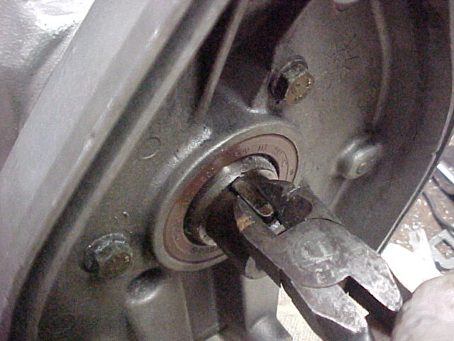
27. Using wire cutters, remove the woodruff key. Pictured is an 8v, but same
idea.
28. Remove the fuel rail vanity cover. It is secured by 4 M4 allen head
bolts.
29. Pull out the spark plug wires from the head, and lay them somewhere out
of the way, like over the intake manifold.
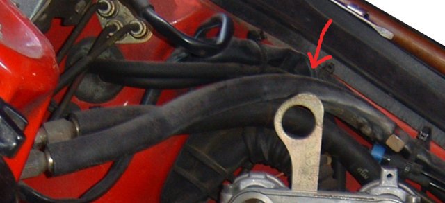
30. Undo the 2 fuel lines from the rail. You will need to use 2 wrenches per
line, one wrench to turn the nut, one wrench to counter-hold the fitting on
the fuel rail. This is very important, because if you don't counter-hold the
fittings they will bend and possibly break. If you are planning to remove
the rail for other purposes, now is the time (and you can just remove the
rail along with these two hoses).
31. With the two fuel lines disconnected, you can tuck them out of the way,
like behind the engine hoisting eye.
32. Unplug the VarioCam wire from the head and put it somewhere out of the
way. You can tuck it under something; I used a zip-tie to hold it to the
cruise control cable, over the intake.
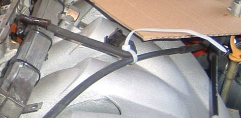
Note, in the above picture, I have disconnected the cruise control cable and
have swung it away from the valve cover. Actually, it's easier to just leave
the cruise control cable connected.
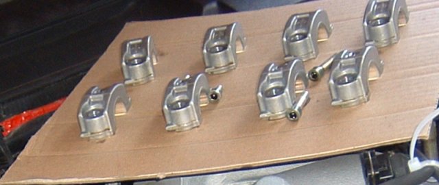
33. Undo the 13 allen head bolts holding on the valve cover. When taking
them out, note where each bolt came from, because there are 2 different
lengths, so it's important to put the bolts back in the correct holes. What
I did was take a piece of cardboard and draw dots mirroring the arrangement
of bolts on the valve cover. Then I punched out the dots. Each time I
removed a bolt, I simply put it into my cardboard "bolt palette". The rubber
donut seals on these bolts must be replaced. The torque spec on these is 7
ftlb.
34. Remove the two small allen bolts next to the VarioCam actuator. Gently
pry off the aluminum collar. The o-ring inside this collar must be replaced,
as well as the gasket that sits directly under the collar.
Note: This is not needed if you are not changing the gasket and seal.
35. Lift off the valve cover and maneuver it away from under the cruise
control cable.
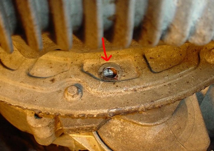
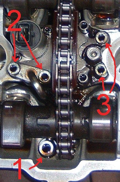
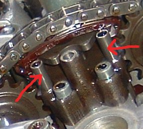
36. With a magnet in one hand, and an allen tool in the other, remove the
VarioCam oil tube's banjo bolt (#1 in the picture), and be careful not to
drop the bolt, or the TWO washers. One washer is below the tube, one above.
The washers are copper or aluminum so they will not be caught by the magnet
so be careful.
Next remove the 2 bolts holding the other end of the oil tube (#2 in the
picture). One of these bolts is really long. Now GENTLY remove the oil tube.
This tube is very expensive. Now the oil inlet of the VarioCam tensioner is
exposed, and there is a little metal ball (with a black metal cuff) sitting
in there. It will want to get lost, so be aware and careful with it.
Next remove the 2 bolts on the right (#3 in the picture).
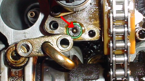
37. Carefully remove the check valve (that metal ball + cuff) from the oil
inlet of the VarioCam tensioner.
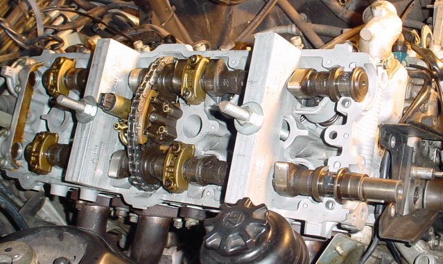
38. You need to undo these 20 bolts.
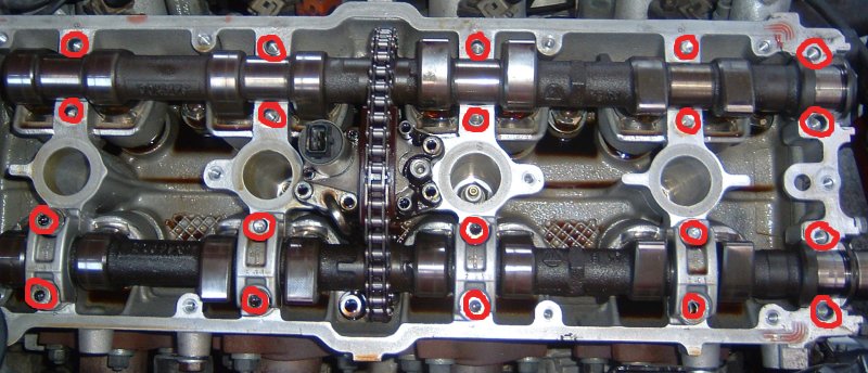
The front 4 go through one solid piece. The other 16 are in pairs, holding
the cam carriers down.
You may end up needing to drill some out. I had to drill out 16 of 20,
because my low-quality tool destroyed the bolt heads. I have since bought a
much better cheesehead tool.
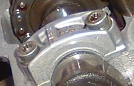
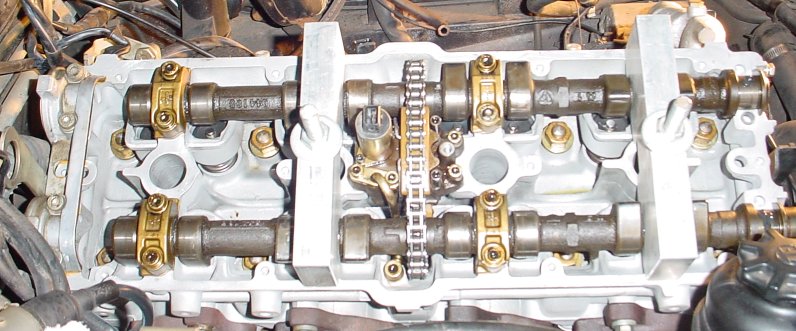
39. As you take each cam carrier (bearing cap) off, be sure to lay them out
properly so you can put each one in the same spot it came from, the same way
it was.
Note: bearing caps are machined with the head they come on, so make sure if
you have multiple heads or cam carriers, DO NOT mix them. The trick to
telling if they are matching is to look in the middle of the head on the
exhaust side by the studs. There is a stamp with the matching number.
When removing the front large piece, also take this opportunity to remove
the cam seal with ease.
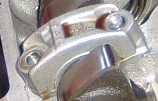
Note: Try to loosen the carrier bolts evenly (all 16 of them) so the valve
springs don't pressure the camshafts into bending. Each carrier needs to
come off straight, to avoid binding the dowel pin. There is a special tool
to help hold things, but being careful and evenly removing the bolts will
work too.
This is the special tool. If you have it, install it first as shown, then
remove the remaining bearing caps, then remove the tool.
40. Lift the 2 cams + VarioCam out of the head.
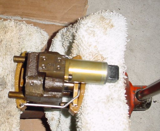
41. Postion the tensioner into a vice or a very good c-clamp. Apply some
light pressure to relieve the pressure on the chain, then slip the cams +
chain off the tensioner. Decompress the tensioner and take out of vice.
42. Remove these two posts using an allen tool.
43. Slip the old tensioner pads off, laugh at how messed up they are, and
slip the new pads on.
44. Reinstall the posts into the tensioner. The posts are loctited so make
sure you use loctite when you put these back in.
45. Swap the chain on the cams, noting the blue links on both chains, and
orienting the new chain just like the old one. The cams should have
triangular "arrows" that indicate where the blue chain links should be.
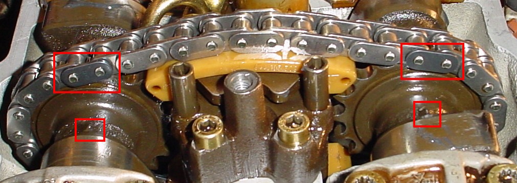
Note: The arrows should be 7 links apart, that's why those blue links are
there. Note that not all new chains have blue links!!! So just count 7 links
(5 links in between them).
46. Put the VarioCam tensioner in the C-clamp (or vice) using false jaws
(towels work) and slowly compress it. If you have special tool 9530, use it
now, and you can put away your vice. If not, C-clamps work better, keep the
clamp on the VarioCam and have patience. Slip the whole tensioner back into
position between the cams and within the chain, then remove the clamp.
Note: I have done this without a clamp as well (just bare hands). My brother
held the cams in the air, and I squeezed the VarioCam into the chain. The
cams must be in the air, not laid on a table, whichever way you do it!
47. Put oil or assembly lube on the surfaces of the cams. Position the cams,
tensioner, and chain back into the head, at the same cam orientation as
before. The blue chain links should be right above each cam.
48. Put oil or lube on the cam carriers. Evenly tie down the carriers with
new bolts, torqued to 15 ftlb. It's impossible to do it perfectly balanced
without the special tool but do your best and it will be fine.
If you have special tool 9248: Remove spark plugs from cylinder #1 and #3.
Place 9248 Cam Saddle tool on bearings for cylinder #1 and #3 in conjunction
with tool 9226 and compress. This will compress the cams evenly. Install
bearing caps after lighly applying engine lube to cam bearing carriers for
cylinder #2 and #4. Torque them to 15 ftlb.
49. When fitting the front cam carrier piece (the one held by 4 bolts), you
must apply a film of loctite 574 to the mating surfaces.
50. Lightly grease the new cam seal, and install onto the exhaust camshaft.
51. Reinstall the check valve (ball and cuff) into the VarioCam tensioner.
52. Install the tensioner mounting bolts, torqued to 7 ftlb.
53. Reposition the tensioner oil tube, using a new o-ring on the
tensioner-side of the tube, and 2 new crush washers on the head-side of the
tube. Torque all 3 oil tube bolts to 7 ftlb.
54. At this stage you can wrap everything up (in a reversed manner of
disassembly). However, if you want to use the factory method of setting your
cam timing, this is the time, with the valve cover still off.
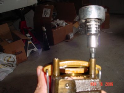
Every part of reassembly is clear except the belt tensioner. It must be
compressed in a vice, and locked with a metal pin (I used a drill bit) in
order to be placed back into position, then the pin is pulled out. Important
to note: There is a "special tool" that MUST be placed on the back end of
the tensioner before you can put it into a vise or clamp. This tool is the
main crankshaft pulley washer! It's hard to get, yes. If you choose to
improvise, either get a spare washer from a junked 944, or find some way of
making the vise or clamp put its pressure on the outer edge of the tensioner
body... not the stepped-up center.
Follow the belt changing procedures to help you put the timing belt back on,
and put the BS belt back on (and aligned correctly for TDC). Don't forget to
put fresh grease on the pivot post for the belt tensioner lever.
Don't forget to use all your new parts.