***This clamp is NLA. See my other page on a replacement with a different design***
New idea about a better flexplate clamp.
I was discussing the TBF and its causes with friends, Bert Vellen and Kees Koese of Koese Engineering. After the usual debate we decided to agree: it takes a proper clamp to defeat the migration of the clamp and prevent Thrust bearing failures. Kees liked the idea and came up with a design that made it to the testing grounds.
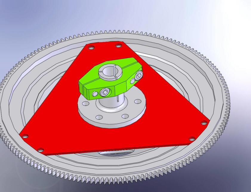
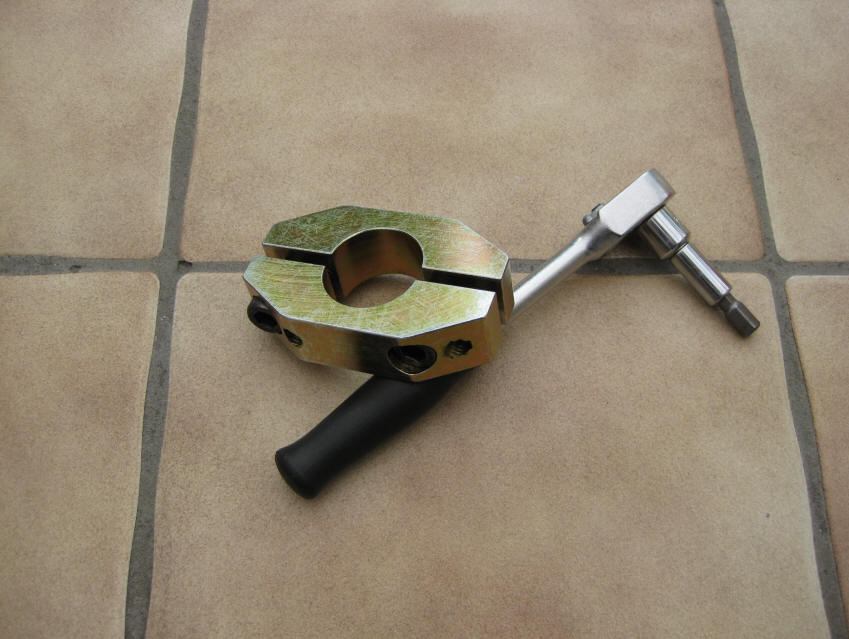
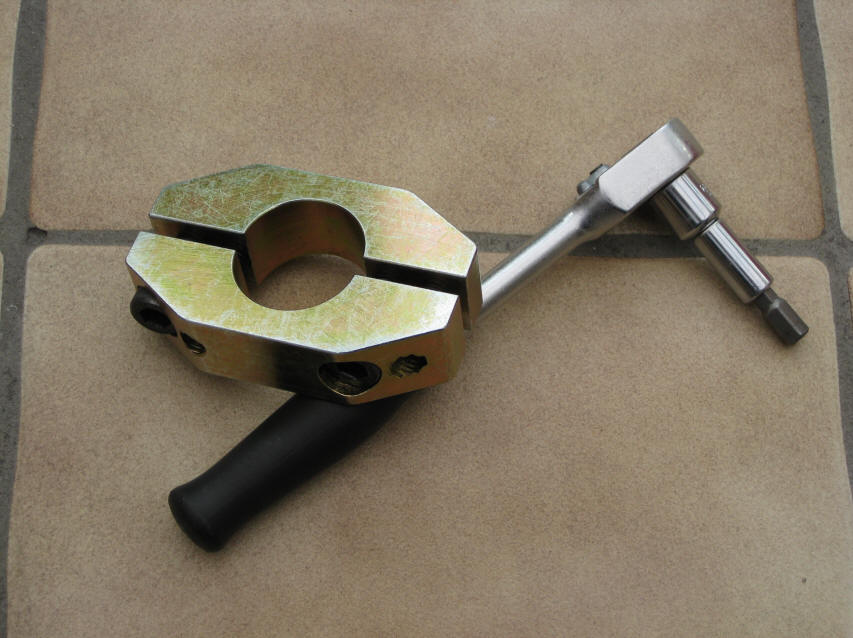
this is the new TT clamp that I fitted.
It is special made and designed by a friend, Kees Koese, and serves to replace
the old flimsy clamp that fails to firmly hold the TT to the flexplate. Slipping
of the clamping eventually results in a huge pressure on the thrust bearing
which will wear fast and ultimately cause an engine failure.
Required tools:
- 8mm hex key
- 13mm ring spanner and socket
- 19mm ring spanner or socket
- large screwdriver
- small (I used a 100mm) grinder
- bit of paint to mark the position
- optional: micrometer to check the crank thrust bearing play
This is a step by step to fit the new clamp:
1. remove the rear side bottom cover of the engine bay. This is 9x 8mm parkers.
2. put a lift under the exhaust to prevent it from fully dropping down at any
time.
3. remove the 6x 13mm bolts that hold the exhaust to the manifold headers. Pay
attention to what comes out where. There is two longer bolts, two brackets and
one distance piece. The distance piece goes between the exhaust and the bracket
at the driver side. The pass. side bracket goes on the nut-side of the bolt,
opposite to the driver side. Remove the large 19mm bolts that hold the bracket
to the engine. That makes it easier to bolt it back later.
4. gently lower the exhaust 2 cm. Not much more, and pay attention to the O2
(Lambda) sensor in the exhaust. Do not pull on that wire, and it is a pain in the
but to
remove the O2 sensor so let it stay untouched.
5. loosen the 4x 13mm bolts that hold the flexplate cover and use a flat 13mm
ring wrench to loosen and remove the 2x 13mm that are just above the cat. These
are the difficult ones. The fairly long bolts need to be loose, don't bother
taking them out first as there is little room. Just take the cover off towards
the engine.
6. enjoy the old clamp for one last time. Turn the engine clockwise until you
can reach the clamp bolt. I do this by using a long flat ring spanner on the
bolts in the flexplate. 15mm I think. That is the easy way. Remove the hex bolt.
7. turn the engine another 180 degrees and use a small grinder to cut through
the clamp. It is fixed to the flexplate bit at one welding point so that needs
to be taken care of too. As soon as you have cut down 80% of the clamp, you can
stop (avoid damage to the flexplate piece). Turn the engine another 180 degrees,
until you see the opening where the bolt used to sit. Use a strong screwdriver
to crack the clamp open. It is fairly easy. Take both pieces of the clamp off.
8. then remove the welding bit that was still on the flexplate piece. It needs
to be nicely flat. Use a grinder or a dremel to make it 100% even.
9. use a strong screwdriver to move the flexplate to the rear as much as you
can. It is just 0,2mm or so, so you won't see a big movement. 0,1 to 0,3 mm is
normal, 0,4mm is the wear limit.
10.
now the beauty comes..... fit the new clamp on the flexplate piece. The flexplate piece on the splines
has 3 gaps, each at 120 degrees. Obviously just one opening will match the gap
at the clamp, the other two will not. Just pick one. Use Loctite 222 (thread
locker,
medium strong, removable) on the M10 hex-key bolts that came with the clamp and
start torque it down at 70Nm (the bolts are high grade 10.9 steel). The outer first. Make sure the clamp closes
evenly, not metal to metal at one side and a gap on the other.
11. make a paint spot on the position where the clamp and spline can be seen.
That will enable you to see any clamp movement.
12. time to bolt things up. Put the two read bolts in the cover and slide it
over the cat just like it came out. As soon as these two are in, the rest is
just reverse of the above. Easy. I always use some heat resistant coat on the
exhaust bolts so that I can still get them off the next time.
The total job takes about 2 hours, mostly opening and closing things.
regards,
Theo
http://928gts.jenniskens.eu
-------------------------------------------------
update April 2015 by Theo.
The clamp holds perfectly. I check it annually and the drive shaft has not moved at all inside the clamp. Perfect. It has been like this now for about 6 years now.
-------------------------------------------------
Here are some pictures of the clamp and the process as described above:
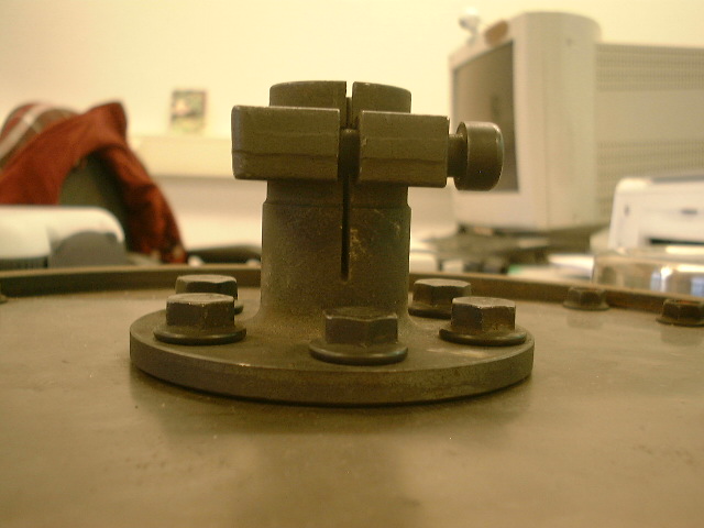
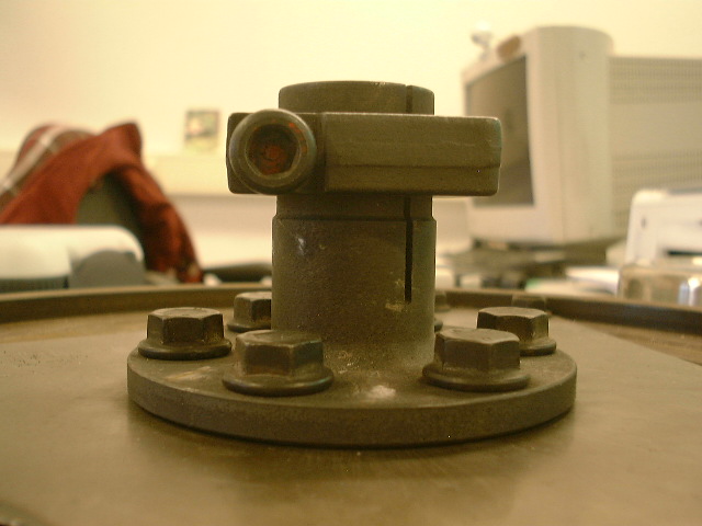
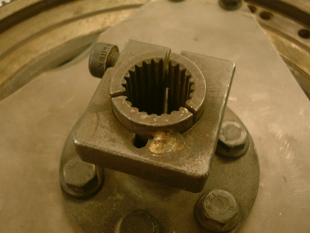
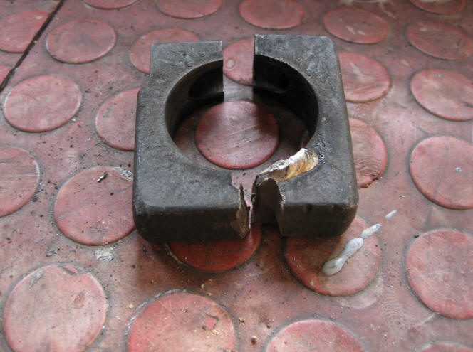
The old one from the side. Notice the orientation.
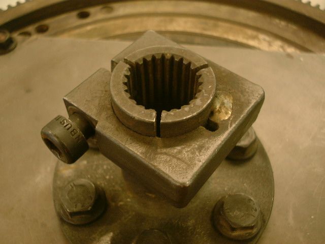
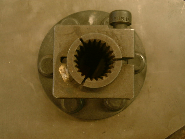
Top view
one more top view
And one to finish
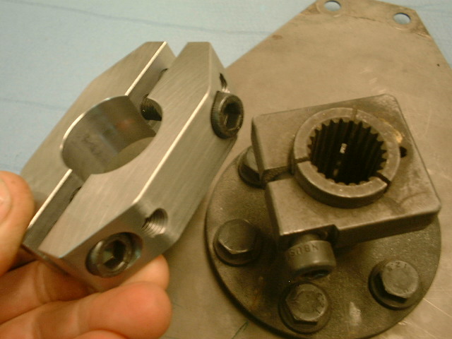
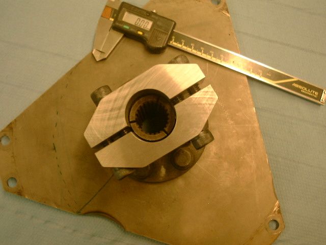
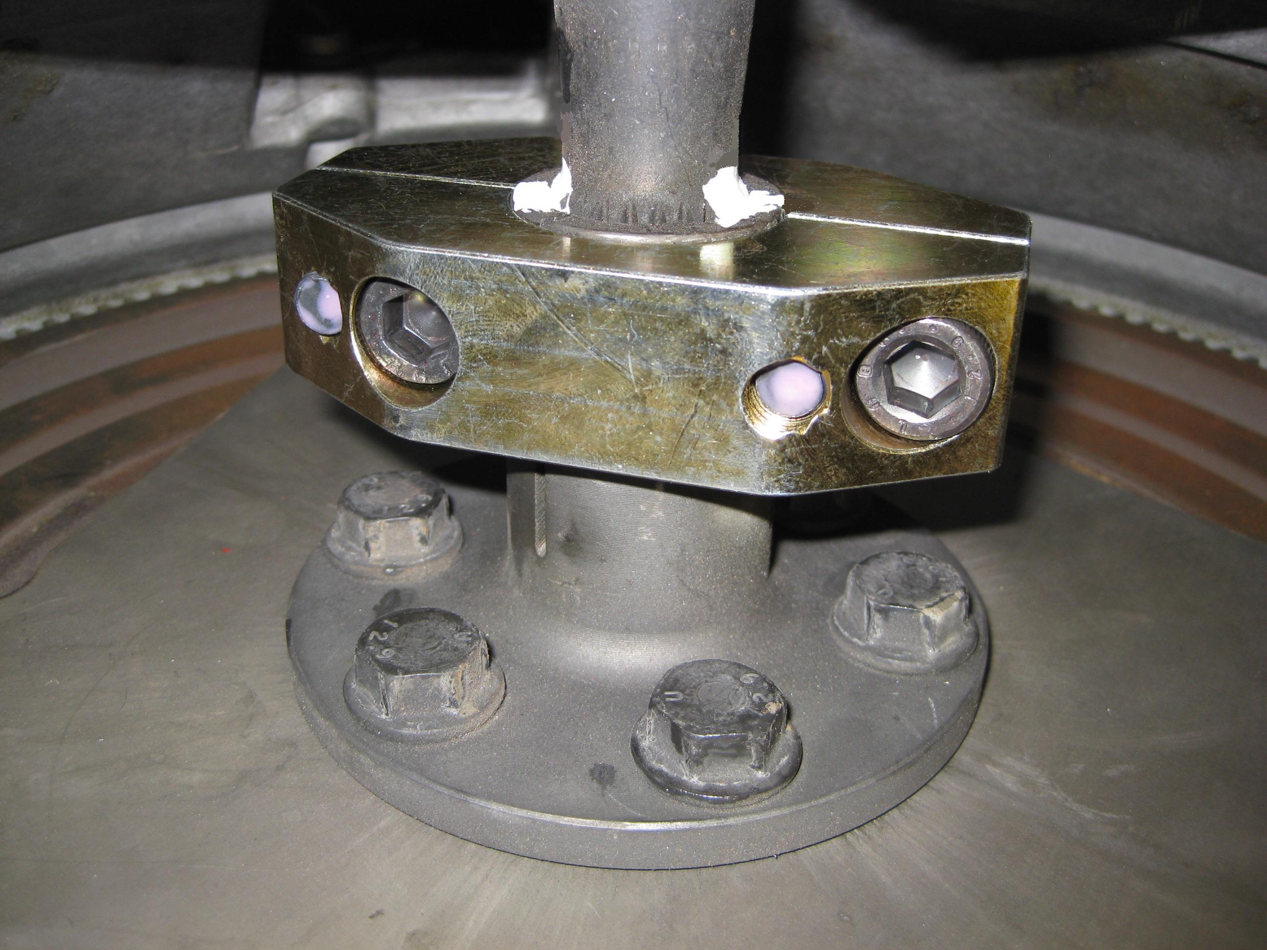
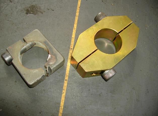
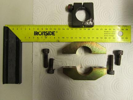
The new clamp compared the the original one. Notice the difference in dimensions. 4 High grade steel M10 bolts (12.9 strength) hold the two half pieces at 75 Nm torque each. That is a lot of combined clamping force. The clamping area is bigger so that the force is spread over a wider range. Tests show 4 times the power of the flimsy original bit :)
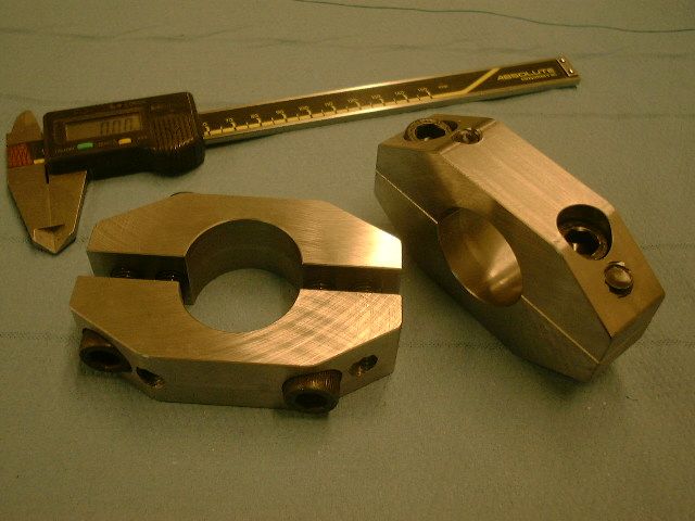
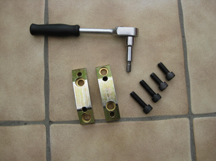
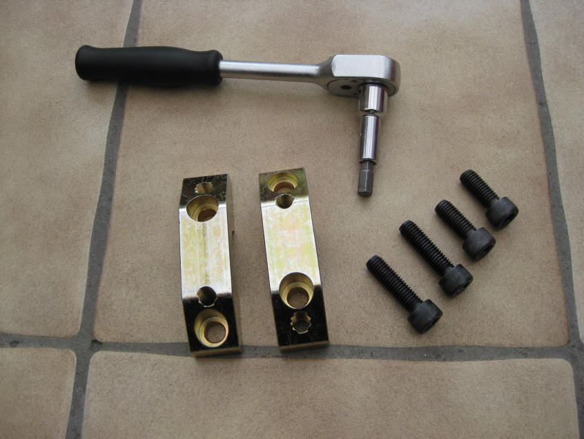
Some pictures of the new clamp:
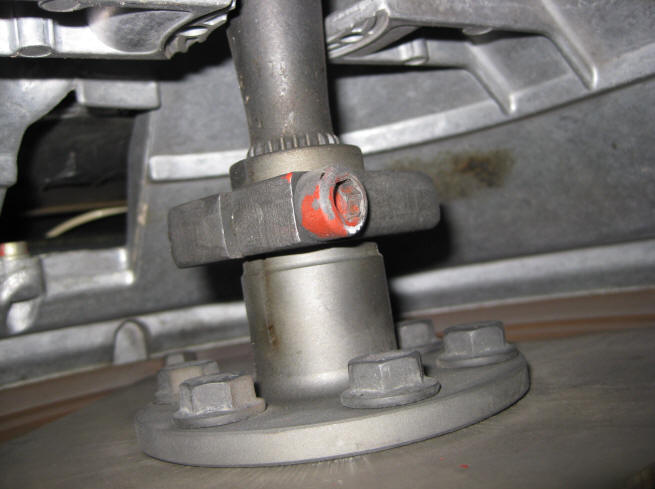
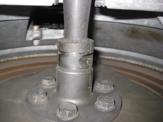
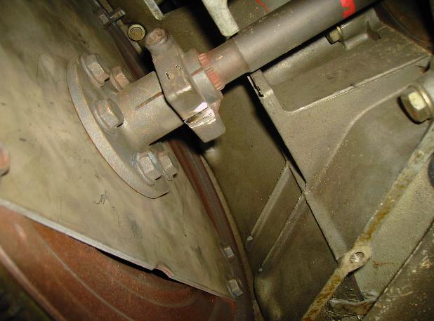
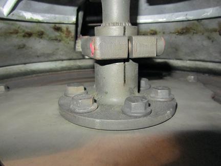
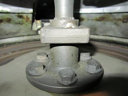
close up of the old flimsy clamp in its tensioned state (pressure on the Thrust Bearing) Spline 3.9mm protrude
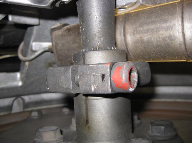
close up of the old flimsy clamp in its released state (pressure on the Thrust Bearing). Spline only 0.7mm protrude
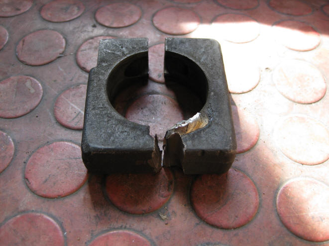
The clamp was cut off with a flex, a 100mm grinder. There was one welding spot that needed to be taken care off.
One more close up
Naked bit, no clamp on it anymore.
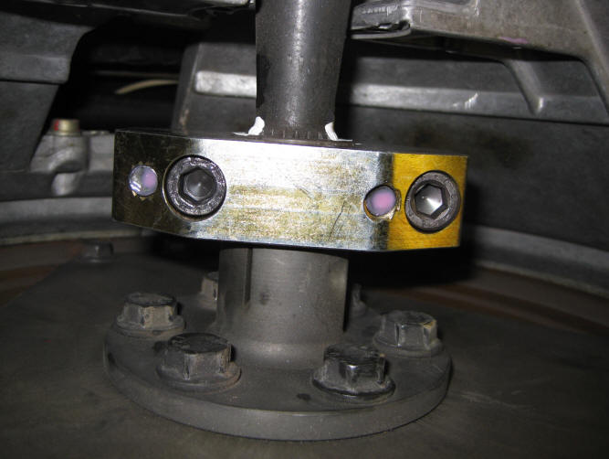
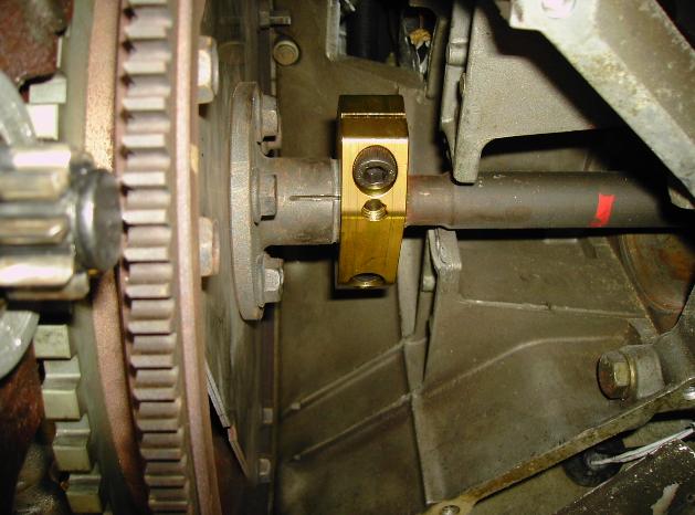
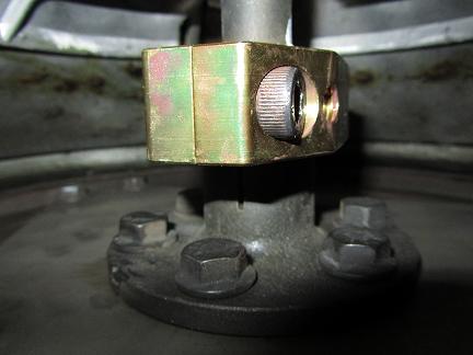
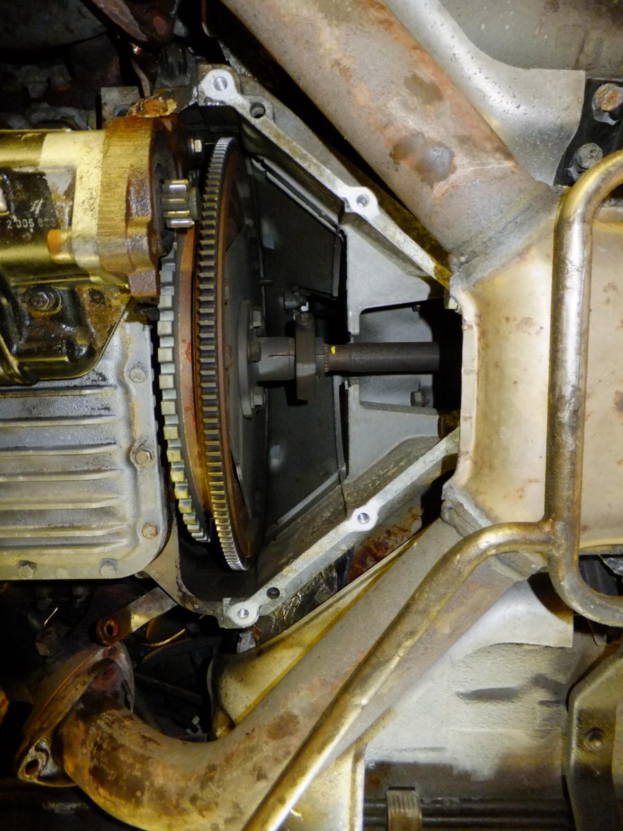
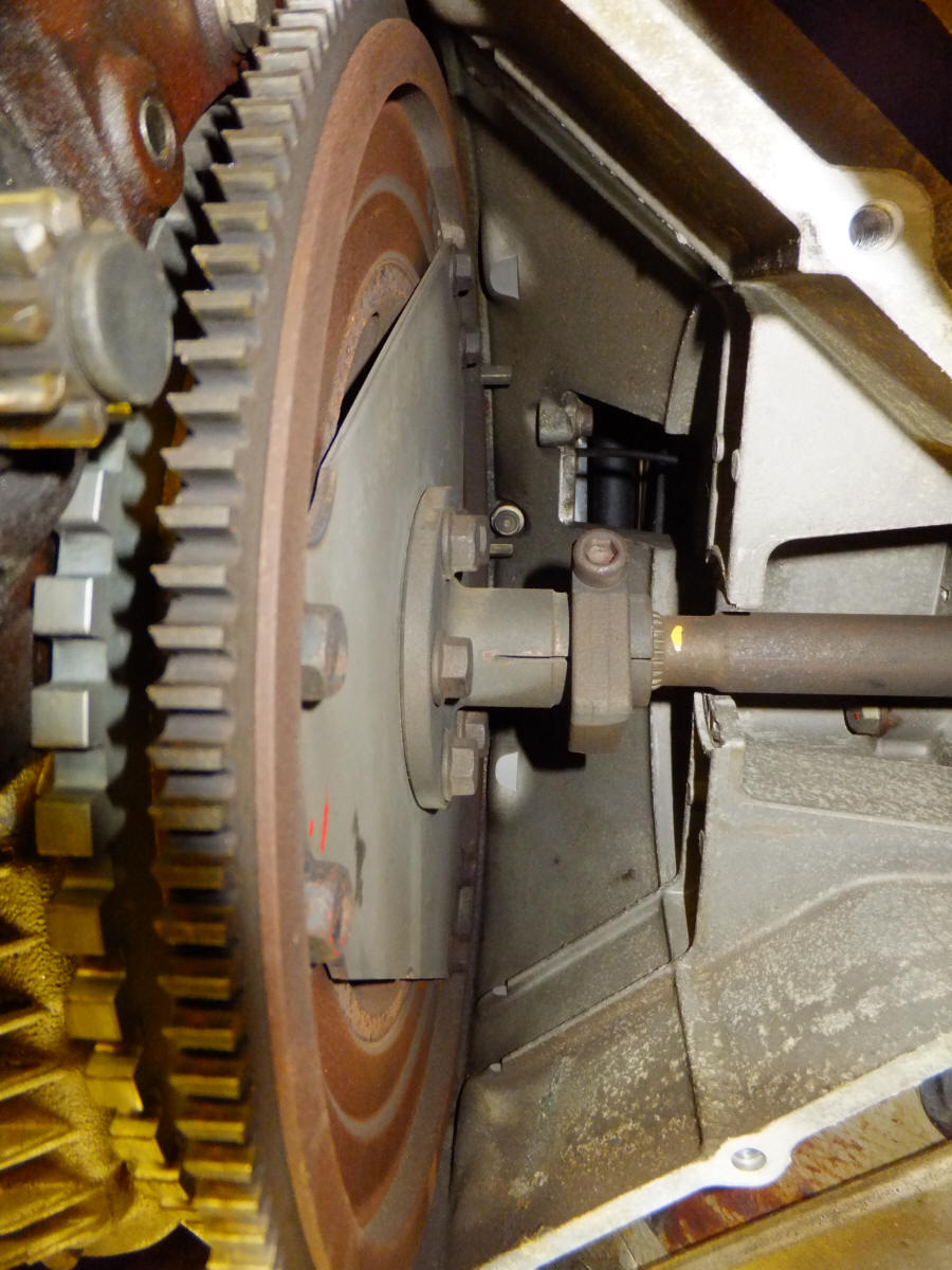
The new clamp fit on the flexplate , strongly holding the spline in place. 75Nm on the 4 M10 bolts. A little Loctite 222 was used to make sure the bolts stay torqued to specs. Also two white paint dots to mark the position so that any creeping can be noticed easily.
Right picture is a camera view through the peeking hole, made in April 2017. You see the white paint that reflects in the light. No clamp migration for 7 years.
_________________
Update on December 2020: I have had the flexplate clamp since 2015 which is 5 years now. All is perfectly well, and I do run the 928 sometimes over 200km/h. So It was tested pretty well. But I need to check the clamp and flexplate next spring. There is discussion about the root cause. If the TT flexes and returns to regular length the provided clamp solution is simply the best. But if the TT flexes and due to micro cracks tends to lengthen or shorten (so the length changes) this may lead to a pressure on the thrust bearing again. This simply need to be verified. The jury is still out on this.
_________________
Dutch version of the instruction to replace:
1. Auto opkrikken
2. Achterste onderplaat eraf
3. Uitlaat bij spruitstuk aansluiting los maken (6x 13mm)
4. Uitlaat wat laten zakken maar zo dat je de lambda kabel niet los trekt of te
strak spant
5. 6x 13mm bout losdraaien van de deksel, en verwijderen
6. Motor in draairichting draaien totdat de oude imbus los kan
7. Speling meten van klem tot einde splines
8. Imbus losdraaien (klem springt terug)
9. Speling opnieuw meten om te zien wat er gebeurd is (+/- 2mm verschuiving)
10. Als je een micrometer hebt de speling van de krukas opmeten: helemaal naar
voren en helemaal naar achteren gedrukt: 0,4mm max
11. Klem zo draaien dat je tegenover de opening de klem kunt doorslijpen. (½
rond)
12. Klem door slijpen of tot deze bijna helemaal door is
13. Krukas weer ½ draaien en een dikke schroevendraaier in de klem opening
zetten, uitbuigen tot ie knak zegt
14. Restant laspuntje waar klem was vast gelast weg slijpen zodat ie vlak is
15. Klem zo plaatsen dat maximaal grip is en dan gelijkmatig aandraaien.
Luchtspleet gelijkmatig dicht trekken tot 70Nm. Gebruik Loctite 222 op de bouten.
16. Ik zet altijd een witte punt om te markeren waar ik hem heb neergezet en dus
eventuele kruip meteen zie (met een lampje door de kijkopening lukt dat al)
17. Alles weer samenbouwen. Op de uitlaat bouten wat witte high-temp smeerpasta doen of Optimoly HT
18. Onderplaat erop.
19. Proefritje
20. Biertje……?
================
Some pictures Rob Meijer sent from his clamp upgrade:
====
This shows what the migration of the clamp look like after some time. Mind the yellow marker.....
Achtung, 928-Fahrer, vor allem von denen mit Automatikgetriebe:
Es gibt eine Schwachstelle im Antriebskonzept, die leider immer noch nicht jeder
sich auf dieses Auto spezialisiert zu haben meinenden Werkstatt bekannt ist.
Das „Wandern“ der Klemmung des Transaxle-Rohres.
Wird das nicht beachtet, kann das zum Exitus des gesamten Motorblocks führen.
Wer das nicht glaubt, ist gerne eingeladen, sich unter dem Thema „Entspannen des
Transaxle“ mal in diversen Fachforen zu diesem Thema zu informieren (danke an
all die engagierten Foren-Teilnehmer).
Die hier angebotene Klemme ersetzt die originale und ist wesentlich stärker als
diese, wodurch die Klemmung spannungsfrei gehalten wird. In diesem Zusammenhang
sicher nicht uninteressant, was Porsche selbst im O-Ton zu dieser Thematik
mitgeteilt hat (Anleitung 9203):
“Following this procedure will ensure necessary clearance for the crankshaft
thrust bearings. Any damage to the engine caused by improper central tube
installation is NOT a warranty matter”.
Mit der hier angebotenen Klemme ist das Transaxle besser fixiert, kann nicht in
Richtung Motorblock „wandern“ und muß daher nicht in regelmäßigen Abständen
entspannt zu werden.
Die Montage ist relativ einfach (das Auto sollte auf eine Bühne hierfür), das
Getriebe muß hierfür nicht ausgebaut zu werden.
Die ganze Arbeit dauert etwa 2 Stunden. Eine bebilderte Anleitung und ein video
(in englische Sprache) kann auf meine Wunsch zur Verfügung gestellt werden.
Dieser Artikel wird von mir als Privatperson angeboten. Sie erklären sich mit
Abgabe Ihres Gebots einverstanden, auf Ihr Recht auf Gewährleistung und Rückgabe
zu verzichten.
Bieten Sie nicht, wenn Sie damit nicht einverstanden sind!