http://forums.rennlist.com/rennforums/showthread.php?t=245964&referrerid=6055
Parts that are needed for the conversion:
1. Dynamic kickdown relay from a '94 or younger car
2. Throttle position switch for the throttle body from the same model year(s)
3. A MAF connector, thank you John Speake for your efforts (this connects the
new throttle position switch to the LH-ECU and kickdown relay).
4. A small plug to connect the extra pin of the new kickdown relay at the
circuit board
5. About 5 feet of standard automotive wire.
First before anybody conciders this conversion: I would only recommend this if
you are taking your manifold off (for whatever reason). The conversion costs
slightly more than $200 and I think this is very competitive to whatever is
available right now.
Here we go: 1st take the manifold off and and unbolt the throttle body housing.
Remove the old throttle switch and replace with the new switch. Make sure that
the new switch "clicks" when the throttle is closed, this is the microswitch for
the ISV activation. Cut of the old connector and wire it according to the
picture below. The white/blue cable activates the ISV, white/red is full
throttle enrichment and brown is simply ground (or earth for Roger).
Sorry, it is a little bit hard to see but the top cable is w/b (idle). Next down
is w/r (full throttle) and 3rd down is ground. Important!!! It is necessary to
run an extra cable from ground to position #5 of the connector. This provides
the variable position signal for the new kickdown relay. The cable in position
#4 provides the signal for the relay and has to be routed to the main CB behind
the passenger footwell.
Down at the CB the old kickdown relay needs to be removed now. The hardest part
was to get the new wire through one of the rubber seals in the firewall. The 2
top screws of the CB need to be removed as well as both ECU's. This will allow
rear access to the panel. The bottom left pin connector on any car older than
'94 is not in use. This is the position where the extra cable will be connected.
FYI!!! The connectors inside these relay bases are different on older cars. The
ignition relay uses the same connector base and I would recommend to talk to one
of the "big three" for the right part.
Old style vs. new style, you will need the internal small connector (it is
simply pushed in). The right connector is for the ignition circuit and if you
look closely you see the difference.
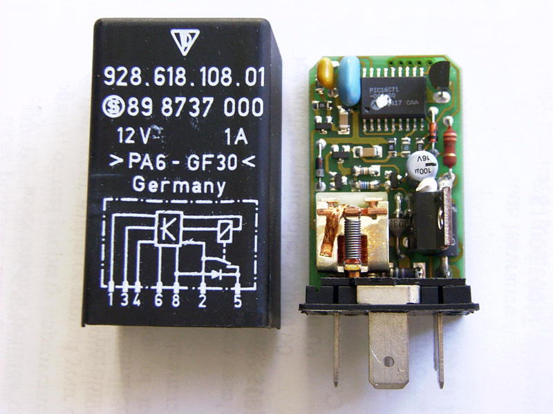
Dynamic kickdown relay with additional pin.
That's it and you're done, your car has "dynamic kickdown". Here is the factory
description when it's activated and how it works:
Dynamic kick-down:
To make the 928 GTS with automatic transmission a more agile vehicle, a dynamic
kick-down has been introduced for model year 1994.
The dynamic kickdown is connected in parallel to the static kickdown. If the
vehicle is travelling at more than 34 miles and the throttle valve is more than
24’ open, the dynamic kick-down can be activated by rapidly depressing the
accelerator pedal a short distance angular velocity > 240*/s).
If the throttle valve is less than 24’ open and the other conditions are met,
the dynamic kick-down is set to standby. If the driver accelerates and the
throttle valve is opened to more than 24’ within 8 seconds, the dynamic kickdown
is also actuated.
After the kick-down has been actuated, this shift program is held for about 8
sec. and then erased. The dynamic kickdown is also erased if:
-the accelerator pedal is released until the throttle valve opening is less than
(24’)
-the throttle valve is closed about 50’ from its maximum opening
-the vehicle slows to less than 34 miles
-the shift point of 4590 rpm in 1st gear or 5950 rpm in 2nd or 3rd gear is
reached.
It is not proposed to retrofit older vehicles for economic,reasons. Apart from
the throttle valve potentiometer, the engine cable harness and the central
electrical system would need to be modified.
Bottom line: There are NO changes if you don't want to! The cars behavior is not
changed unless YOU want to and it's all available with a crisp step on the
Bwwwwaaaaaahhhhh pedal. Even without pressing it completely down, nice .
The car is much more agile to drive and is very responsive, I like it very much!
I also tried the automatic tranny cable tightened method and it is not
comparable, because the shift points are always later.
This can also be done with the famous parallel kickdown switch from Radioshack,
correct. BUT regardless where you place the switch you have to move your hands
of the wheel. This modification gives you a "dynamic" car without sacrificing
safety in my opinion and it is just like the factory designed it.
Before I forget: To my knowledge this conversion can be done on all 1987 (S4)
models or younger.....
__________________
Schocki
--------
I’m currently installing this GTS Dynamic Kickdown Modification on my 90’ S4.
Here’s what I’ve done so far:
1. Remove the S4/GT/GTS intake manifold.
2. Installed and adjust the new replacement GTS Throttle-Valve-Switch.
3. Rewired engine wiring harness at the under the intake manifold location, to
include the 6-position MAF type AMP connector. This also includes a new wire
that’s routed directly to the later GTS Kickdown relay.
4. Route new wire along the engine wiring harness and through the firewall to
the fuse/relay board (Central Electrics Panel or CE).
5. Reinstall the S4/GT/GTS intake manifold.
Here’s what I still need to do (waiting for parts):
1. Install a new relay socket pin terminal where currently unfilled.
2. Wire socket pin terminal to “V” connector at bottom of CE panel.
3. Install the new GTS Kickdown relay.
4. Connect the new wire from firewall to the V connector, pin 22 (V22).
Schocki did a great job describing this mod, but here’s some details that he
left out:
A. Parts List for this mod:
From Porsche:
1 – P/N: 928.618.108.01, Relay Kickdown, $57.07
1 – P/N: 928.606.157.01, Throttle-Valve Switch, $101.38
From JDS (www.JDSporsche.com):
1 - 6-position AMP Connector w/ Rubber Boot, $37
From Eagle Day (www.eagleday.com):
9 ft. Thinwall (TXL) Automotive Wire, stranded, AWG-16-18, color: Yellow/Blue,
$6
From any Automotive Store or HFT
6 ft. ¼” I.D split loom, convoluted tubing, $2
10 (maybe more) – Nylon cable ties, $2
Other electrical items:
Still sourcing parts for the fuse/relay panel (will update this later), $?
B. Throttle-Valve-Switch (TVS) Installation/Adjustment
This must be done with the S4/GTS intake manifold removed from the engine bay.
The TVS is installed with two set screws. It’s a simple matter of removing these
screws, removing the old TVS and installing the new TVS, and reinstalling the
two screws. But before tightening the setscrews, adjust the idle switch by
rotating the TVS in the mounting bracket.
Use the WSM wiring diagrams to compare the 94' GTS to earlier automatics. The
plug pin numbers are indicated on both wiring diagrams. TVS Sensor pin number
are only indicated for 94 GTS. Don't confuse plug and sensor pin numbers as they
are assigned different numbers.
Here's a table. TVS pin numbers indicated:
94' GTS, S4/GTS -93'GTS, function
pin 4, pin 18, ground
pin 5, pin 3, loaded throttle
pin 6, pin 2, idle
Yes, pin 18 is correct and not a typo; just like what is shown in the photo of
WSM Vol 2.
For my S4, I used a feeler gage and continuity meter to check the idle setting.
Under the manifold at the throttle valve, there is an adjustable stop for the
throttle. Placing the feeler gage between this stop, and measuring continuity
between pins 18 and 2, I found:
- with a 0.006" feeler gage, meter reads continuity,
- with a 0.007" feeler gage, meter reads open circuit.
For the new GTS TVS adjustment, I'd suggest adjusting it until you get the same
result, measuring continuity, per the above table, at pins 4 and 6.
C. TVS Harness Plug Wiring
Just a simple matter of cutting off the old connector and installing the new
connector. Use the proper crimping tool (Radio Shack) to make a neat crimp. The
wiring harness has plenty of wire to allow installation positioning of the
intake manifold with the TVS connected, still, cut off the connector as close as
possible.
Here’s a table of the wiring new/old:
94’ GTS, 90’ S4, function
pin 1 (WT/BL), pin 3 (WT/BL), idle
pin 2 (WT/RE), pin 1 (WT/RE), load throttle
pin 3 (BR), pin 2 (BR), ground
pin 4 (YE/BL), N/A, kickdown relay
pin 5 (BR), N/A, ground
pin 6 (not used), N/A, not used
Again, these pin numbers are for the harness connector, not the TVS pin numbers.
Seal the end of the rubber boot with silicone cement (RTV) to prevent moisture
intrusion. Route the new kickdown relay wire along the engine harness using
cable loom (split convoluted tubing) and nylon cable ties.
D. Kickdown Wire Routing through Firewall
The engine wiring harness makes a 90 degree turn at the firewall, so routing the
kickdown wire through there is not possible. There’s really only one way to
route the kickdown wire through the firewall, but its hard to see.
There’s another small wire harness penetrating the firewall, just two inches to
the outboard side of where the engine wiring harness goes through the firewall.
You can’t see it from the passenger compartment side because of all the
insulation and wiring. And can’t see it from the engine bay due to the coolant
reservoir blocking the view. There’s actually a small grommet installed and the
harness is only about ½” diameter.
So you need to feed the wire through this small grommet. Do this by using a
stiff wire to open the way for the wire. I used six inch long piece of 14 gauge
bailing wire. File the end blunt so as not to gouge the harness and use some
dialectic grease to lubricate the end.
With the wire inserted through, slip a three inch long piece of 5/32” tubing
over the bailing wire, and slip it through the grommet. Now you can remove the
bailing wire and have a conduit for running the kickdown wire through.
After routing the wire through the firewall, you can remove the 5/32” conduit,
but I”d use a ohm meter check the conduit for short to chassis ground, as a way
of ensuring the grommet is still doing its job and will also protect the
kickdown wire from shorting to ground at the firewall.
That’s it for now. I’ll update this thread when I have completed the wiring of
the central electric panel.
borland
90’ S4
--------
Borland asked me via PM what the Ohm resistance values are with the new throttle
switch.
Here they are for all:
Idle: 0.5 Kilo Ohm
Full: 3.35 Kilo Ohm
__________________
Schocki
--------
The relay is a special one. Barry took one apart to have a look. You can see the micro controller chip 16C71 who had the program stuff isnide