Originating from Rennlist:
Anyone defeat portions of the bulb control module? I've been wanting to
defeat the third brake light so I can replace it with an LED.
I've got a spare bulb control module (p/n 928.641.603.07). Took off the cover.
Looks pretty simple. Automotive application IC's. Found a datasheet on a similar
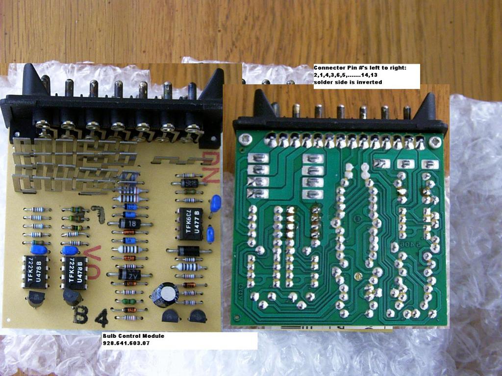
bulb control IC. Here's the photo of the circuit board:
I pasted the inverted solder side next to the component side. You can see the
sheet metal shunt resistors. The circuit basically measures the voltage drop, in
milivolts, across these shunt resistors. The shunt resistors are in series with
the incandesant bulbs. Marker and brake lights are the only bulbs that are
monitored by this unit.
borland
90' S4
_________
Borland & Ed - just swapping the load resistors should be enough. The lamp
control module just senses that the voltage drop across the resistor when the
load is turned on is enough to indicate the bulb is not burned out (and
presumably also is not so much you have too powerful of a bulb installed).
So there is a voltage window comparator... however its configured.
So a higher value Rx should work - you'd need some trial & error to determine
but a ratio of the Bulb Current: LED Current should be close to the Needed Rx
value: Existing Load Rx value. You will not need anything like such a high power
load Rx - 2W ceramic should be perfectly OK for a typical LED bulb (but maybe
not for a 3W LED version).
Another way to do this is to monitor the voltage across the load Rx's when the
correct bulbs are active - then match that voltage drop for your LED's
Alan
__________________
I see from the data sheets that the threshold voltages are 53 mV for the U4791B
and 8 mV for the U4790B; that's the main thing I wanted to know. Now it's just a
matter of a few details like what shunts are hooked to what bulb sockets, what
LEDs we're using and their current flow at normal voltage, a little math, some
adjusted shunts, and Bob's your uncle.
BTW, borland, thanks for taking the time to pull your module and get the IC
info. It's nice having the right data sheets for the ICs used in our 90s.
__________________
I'm finished with the mod and experimenting...
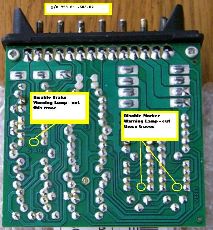
To verify cutting the traces defeats the bulb monitoring, I cut the traces for
the Marker Lights. It does disable the digital instrument cluster's "Tail Lamp
Failure" message. On the cars with digital display, you have to start the engine
and wait for the digital display message. Headlights or parking lights need to
also be turned on also.
Later, I also cut the trace for the brake light and verified the same defeat for
the Brake Lights monitoring.
Restoring the traces is easy if you keep the cuts narrow. All you need do is to
tin the copper plating on both sides of the open trace, de-flux the cut area
with a solvent, and then apply a drop of solder from the soldering iron. The
trace will wick off enough solder to bridge the gap. Confirm the joint is
restored with a ohmmeter.
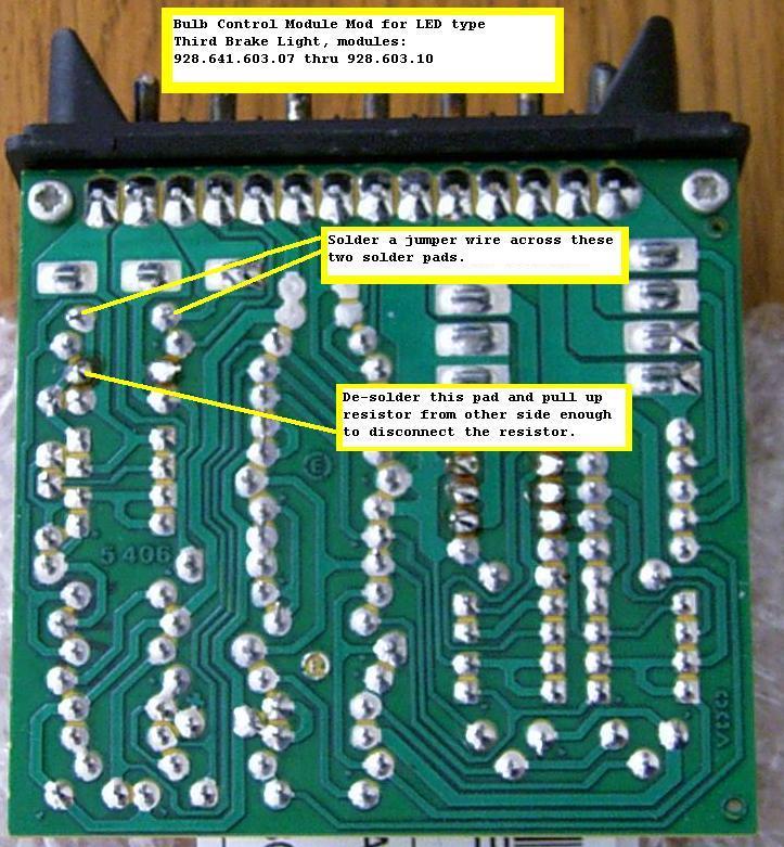
I also modified my module to allow an LED replacement bulb for the Third Brake
Light. It works great; no faulty warning message. With this mod, if the other
incandescing brake light bulbs fail, the warning feature will still work. If the
LED fails alone (>10,000 hour typical life, so highly unlikely), then no
warning.
Here’s an annotated photo describing the LED Third Brake Light circuit board
mod:
I’m not recommending anyone do this to anyone's car, as it defeats the car’s
original design safety features. Just documenting what I did and the results.
________
Pulled the module on my 90' S4.
Quite easy to do on the 90' and later cars. The module resides just to the
outboard side of the glove box. Simply remove a triangle shaped carpeted piece
(three screws), open the glove box door and remove a couple more nuts that hold
a bracket in place, and the module drops down along with a alarm module.
The module on my 90' has a later part number, # 928.641.603.10. Taking the cover
off.....
- same printed circuit board as in the photo previously posted,
- same component count. Only difference is the ICs are of a different part
number.
- uses Telefunken U4791B and 4790B special automotive application ICs.
So, different part number but same basic circuit.
borland
90' S4
Here's are datasheets of those chips:
U4790B datasheet.pdf U4791B datasheet.pdf U477b Connection Diagram.pdf
------
Hello Dan,
The bulb monitoring is built on a small valued resistor (wire) over which the
voltage is measured, and if it exceeds a certain margin the alarm is sounded. So
yes: it measures current in the independent bulb chains. It is compensated for
the PTC effect of the bulb filament. This might be useful to you:
http://jenniskens.livedsl.nl/Technical/Tips/7/MyTip752.htm I even got
the datasheets of the comparators :) Reminds me I must put the U477B/U478B on
line as well. The U477B is 16mV, the U478B is 100mV.
Since the current is rather high, you're looking at a low shunt resistor of
milli Ohms. So any contact problem at both alarm unit as bulbs themselves will
cause a warning.
12v battery, 5W bulb, 5/12=0.417A, trigger is 100mV, so shunt resistance for a
5W is about 240mOhm. Not much.
I'm not really sure but it looks like they hooked up brake lights on two
comparator inputs on 477 (54L/#13 and 54R/#11) and the tail lights with side
markers on 4 separate chains using two dual 478 (58R #3/#4 and 58L #1/#2). There
are two separate warnings: #7 reports a brakelight warning, #10 reports a
taillight/sidemarker warning
The blinker is not wired to the bulb controller box, but it shares the ground
connection. If that one also has problems (slow blink) you're on to bad grounds
or bad power.
So....you probably have a ground contact issue, wrong/bad bulbs, low on 12v
power for the bulbs (when lit), or a defective warning box.
Oh, and don't forget to check the front and side marker bulbs. They add to the
current.
regards
Theo
1992 Porsche 928 GTS Midnight blue
The Netherlands
http://jenniskens.livedsl.nl
http://928gts.jenniskens.eu