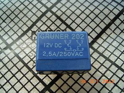
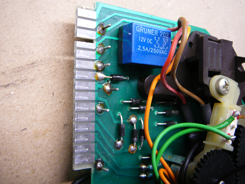
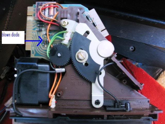
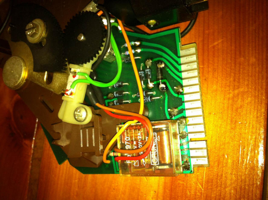
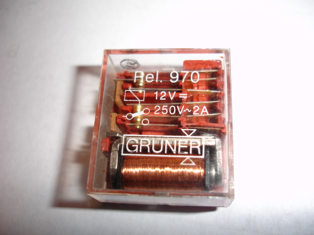
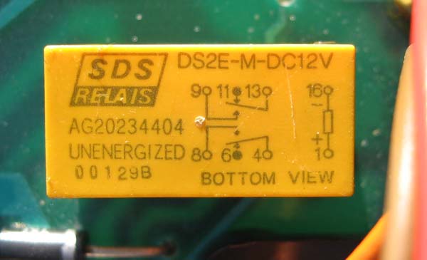
This is the original Gruner 202 relay in the control module. As you can see, the relay coil is located between pin 5 and 8. Quite uncommon. The relay is a form 2 relay, DPDT style. The contact rating is 2,5 A and the coil takes 52mA when engaged at 14v.
The load of the clutch is 2-4 Amps, a generic coil resistance is 3-5 Ohms. I guess the Gruner relay is not even properly dimensioned it seems....
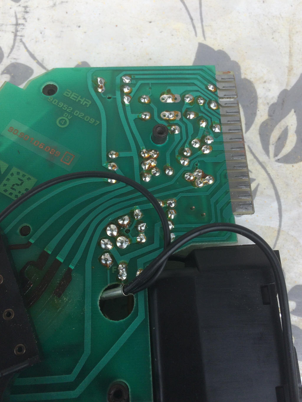
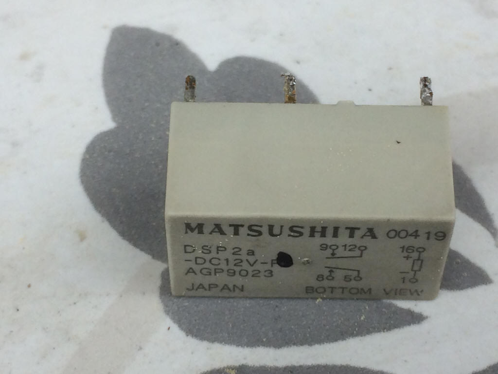
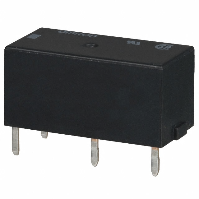
I used as replacement a 35mA version with 8A contact rating, dimensions: 29x12.7x15.7mm. This fits nicely upside down between the contacts (some Polymax adhesive to fit it into place) so that you can wire it down to the pcb just as you like.
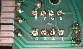
This picture (Dwayne's) shows the overview of the relay in the pcb. (actually he made a mistake, the pin numbers on the relay were reversed, I corrected this)
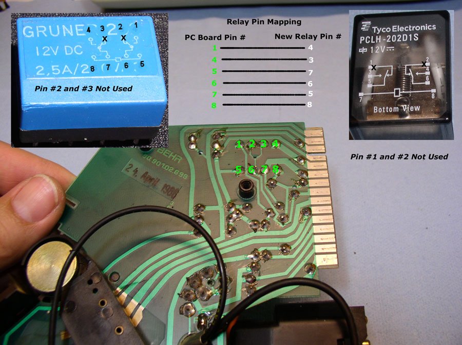
It shows that pin 2 and 3 are not used. If you look at the pictures that seems not true. But if you look more carefully you see that the pcb is drilled in the intersection of where #2 and #3 seem to attach to #6. Originally they intended to make that connection it seems....
Bottom line: take a proper (5A?) physically small but capable relay, fit it in if possible and use wires to connect the signals to the pcb. It is unlikely that you will find a relay that is a drop-in.
Y'all,
Many thanks to all for guiding me on fixing my AC. I replaced the little blue
relay (LBR) on the AC control board with a relay from Radio Shack. All is cold
now. I'll be watching for leaks from the compressor.
Here's some notes from my experience replacing the relay that isn't covered or
is different in the info from Theo's website. Hopefully, this will help save
someone some time. This is for an '87 928.
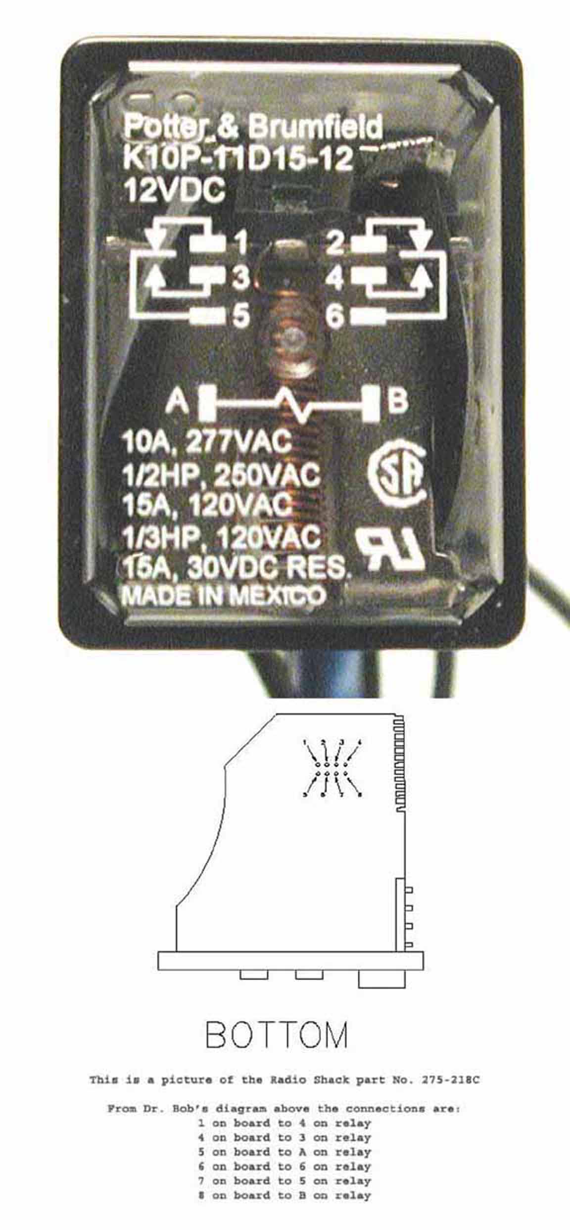
The RadioShack part number is 275-0218. It is made made by Tyco with P/N PCLH-202D1S.
Cost was about $9.19 with tax.
I found that the schematic printed on the LBR did not match up with reality.
After making the translations from one relay to another, the fix did not work.
The relay did pull in when the AC button was pushed, but nothing else. After
checking voltages at the new relay's prongs there was at least 3 wires in the
wrong place. I needed to refer to the wire diagrams to determine the proper
hookups. I'll try to describe the board layout and the connections to the new
relay:
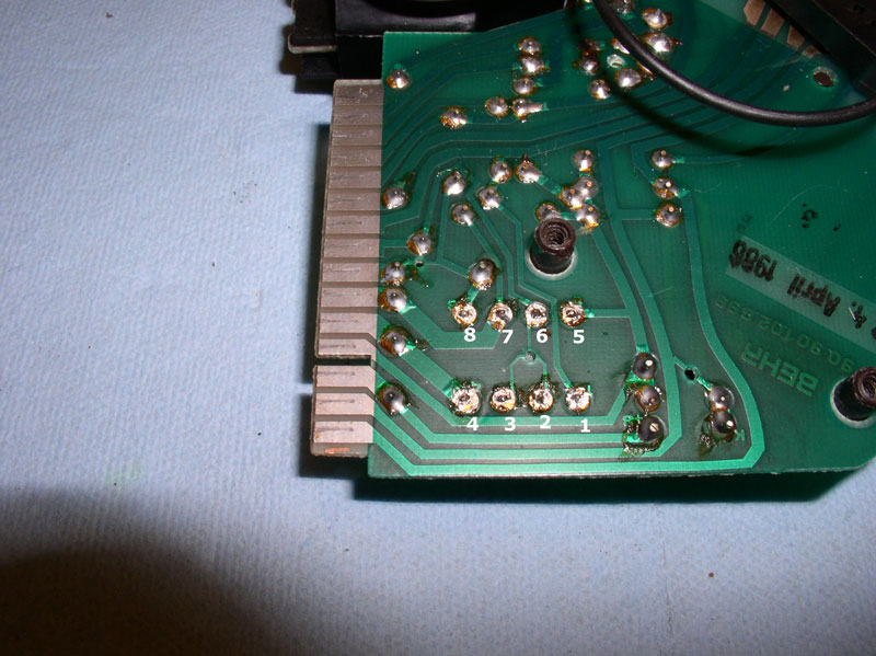
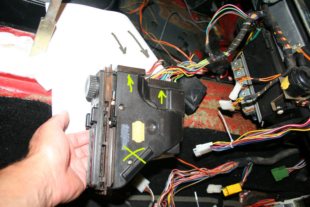
With the controller board turned over and looking at the back you'll see the 8
LBR holes, 2 rows of 4. They will be numbered as such:
1 2 3 4
5 6 7 8
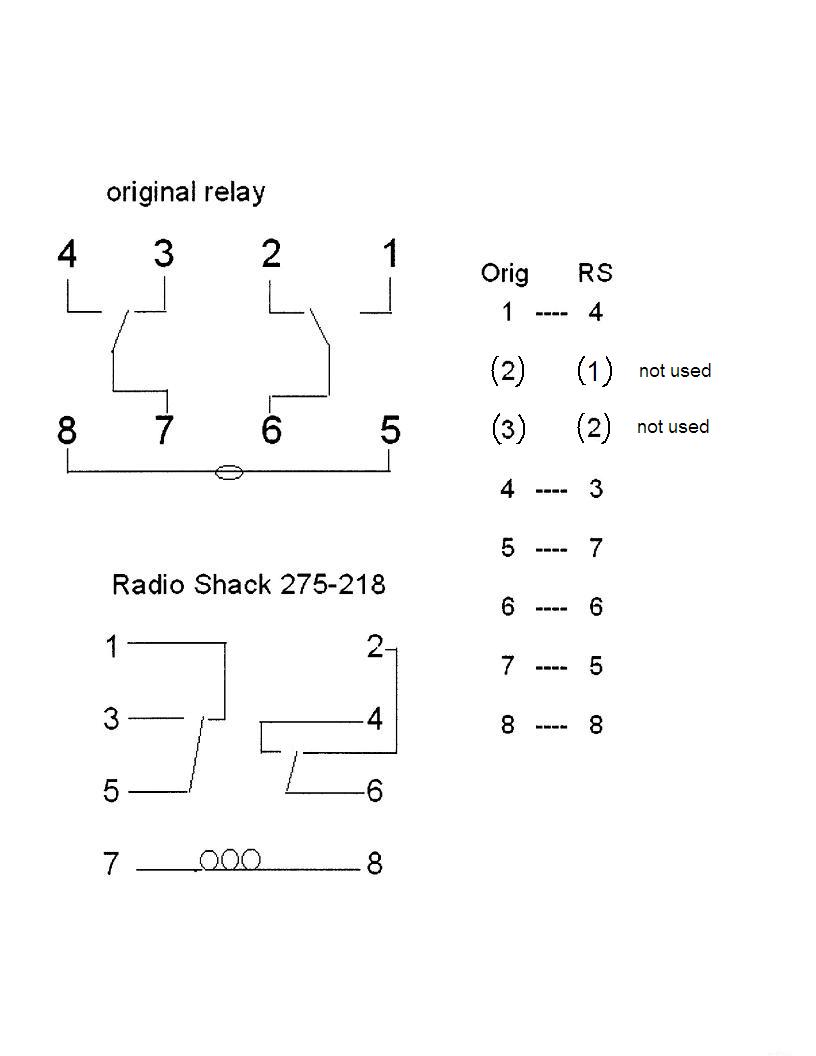
The connections I made to the pin numbers on the new relay:
LBR RS
1 4 (switched on)
2
3
4 5 (12v)
5 7 (coil)
6 6 (12v)
7 3 (switched on)
8 8 (coil)
I hope this helps.
Brian Scudder
'87 928S4 with working AC fixed for $9
(to be honest: this looks to me like an awkward solution... (red. Theo))
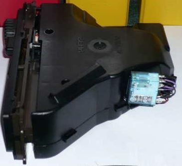
HVAC control unit modified with an upgrade relay since the original is too flimsy to operate the AC clutch properly.
Power flow of the Relay:
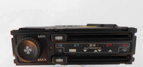
HVAC console detail 1991 model S4 GT
======
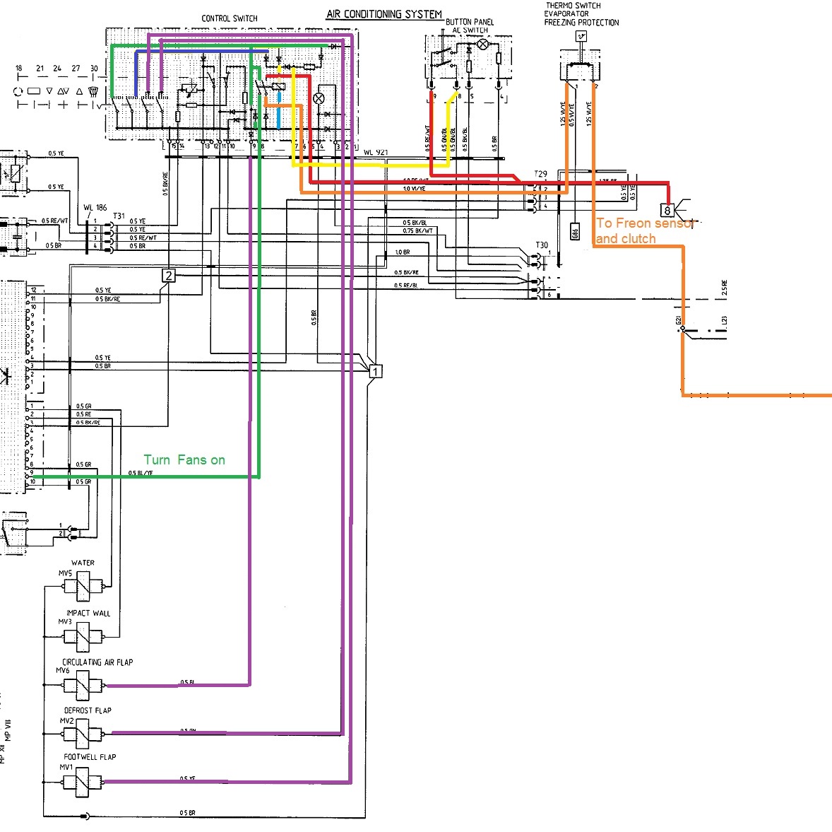
So I've been tracing the factory schematics to try and determine the correct
orientation of the Radio Shack 276-0218 relay when replacing the odd pinout of
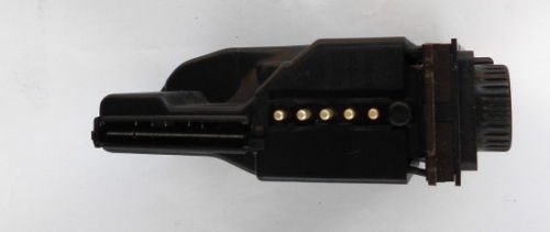
the '83 and '84 model year Gruner 970 relay. The Gruner 970 does not have a
schematic on the case like most relays. Furthermore, the pattern of the relay
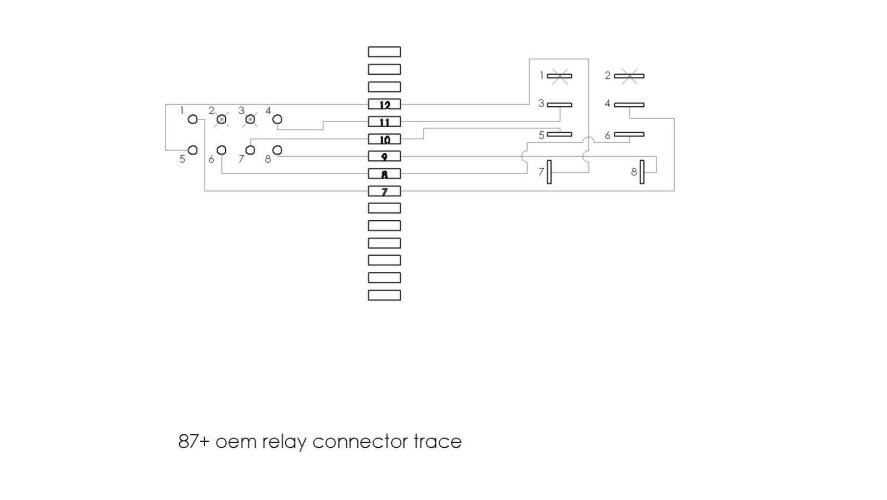
itself is different than the parallel 8 pin configuration of the 87+ relay. It's
more of an offset 6 pin relay with 2 separate pins that are indeed the coil.
What I have found is that although the boards are completely different in
design, the pins on the connector are identical in where they go on the control
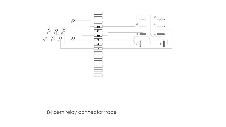
board. So I created a drawing of the original mod provided by Dr. Bob that
includes the connector pin numbers. This 1st drawing shows the 8 pin original
location with the Radio Shack relay on the right. I've included photos borrowed
from Dwayne's HVAC relay repair thread, others that show the Gruner 970 relay
for reference, and closeup photos of my 84 HVAC board. I've also attached the
schematics from the 87 and 84 model year AC head.
I then created another drawing that traces the relay pin holes that correspond
with the connector pin in the opposite direction to determine the correct
location for the new relay.
I'm not completely sure this is correct. I've poured over drawings and
schematics from the different model years and I'm pretty sure it's right, but
I'd really like to get a confirmation from any or all of our resident electrical
geniuses before I start soldering.
I've got a new diode to replace the burnt one on the board and I'm itching to
get going. Hopefully this process won't give you as much of a headache as it's
given me...
If this all works out, I'll post the results to Dwaynes HVAC thread to help
future victims. I sure hope this is correct... I'm ready for cold air again!
Thanks!
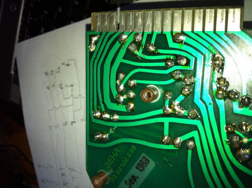
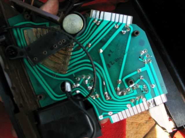
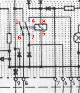
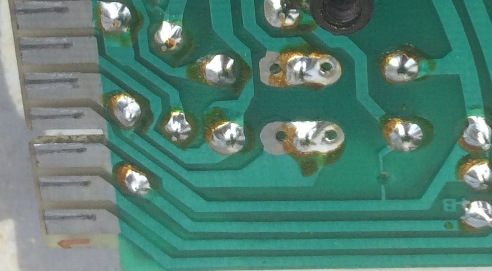
This shows a close up of the GTS style PCB and you see that the middle pins are merged as one, which makes selecting a replacement relay easier
This shows the earlier pcb with the middle contacts separated and functionally different. I´d say select a relay that is identical.
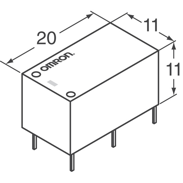
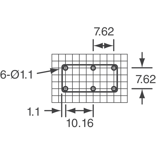
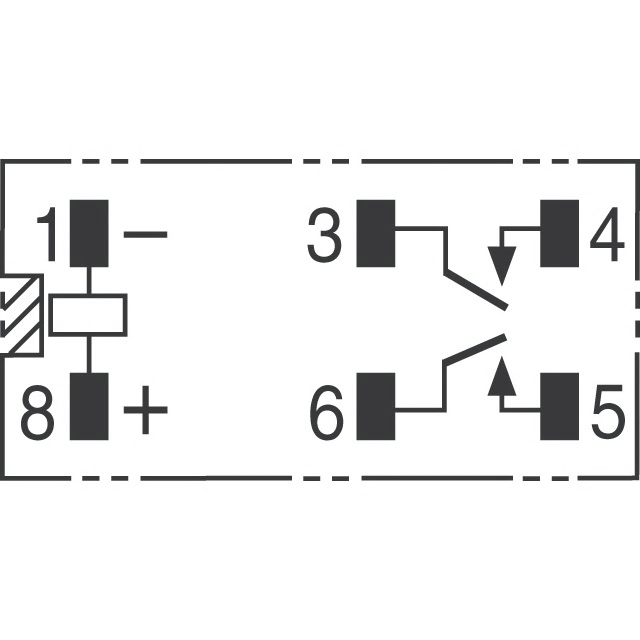
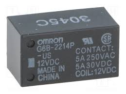 OMRON G6B 2214 P 12v