The Hall sensor is timed fairly accurately relative to the camshaft. I am not
sure that the Hall is the reason for the delay in the engine firing, that is
more likely the EZK sorting out where it is relative to the gap in the teeth of
the timing ring (flywheel).
The Hall is used to help the EZK work out which cylinder has detonation. The EZK
then retards the ignition on a per cylinder basis. Clever stuff...
If the flywheel speed sensor fails, then the EZK uses the Hall signal to give a
"get you home" spark timing, although this is not as accurate as the flywheel
sensor.
__________________
John '86 Euro S2
--------------
On my EZK test jig, if I am testing an EZK ECU and I switch off the Hall signal,
then the ignition retards by the expected 6 degrees at high loads/rpm. If I then
switch on the Hall signal, it still stays retarded.
If I switch off the ignition, and on again, with the Hall signal restored, then
normal timing is resumed.
I will remember your experience.....we are all on a learning curve about the
mysteries of the 928's electronics !
Regards
__________________
John '86 Euro S2
----------------
"If the flywheel speed sensor fails, then the EZK uses the Hall signal to give a
"get you home" spark timing, although this is not as accurate as the flywheel
sensor."
- John Speake -
Actually. once the flywheel sensor fails, the engine will die as there's no
information from the Hall sensor to keep the engine running other than a TDC for
a certain cylinder, or a relative engine timing position versus the cams.
Furthermore, a Hall sensor is really not needed to determine which cylinder
needs to be retarded because of pinging, but Porsche decided to use it for this
purpose on the 928. A Hall sensor (cam position) is really only needed for
sequential injection. Even for direct ignition, the ECM can determine the
proper timing relative to a TDC crank sensor.
"I had heard of another instance where the Hall sensor fault was not cleared by
a battery disconnect."
There's NO non-volatile memory device in either the LH or the EZK ECUs.
Thus, once the battery voltage is removed, both ECUs lose their faults.
__________________
Loren
------------------
The fault codes are stored in an SRAM (volatile memory) in the diagnostic ECUs.
The codes are maintained by a permanent battery supply. In most cases, the codes
can be cleared by a battery disconnect.
The only case contrary to that, which I am aware of is the Airbag controller of
the 928 which requires a diagnostic tester to clear the stored fault codes.
__________________
John '86 Euro S2
JDSPorsche.com
-------------------
Joe,
If the sine is fixed at 60Hz despite of rpm of the car, you are looking at
background noise from the 110v electric circuits. If it is related to the rpm of
your car, that will make me reconsider :) It is possible that some Bosch sensors
have a signal amplifier and shaper to produce that nice (digital) square wave
form. I can't tell for sure.
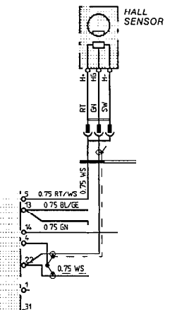
Your 928S4 has +12v from the EZK going from pin 5 to the sensor on pin 1, and
has ground from the EZK pin 4 to the sensor pin 3. EZK pin 22 is the signal
output which is shielded by the ground connection. The sensor conducts when the
marker passes, and switches the +12v to ground. 12v could also be 5v, not sure
about that. That is how I think it works. I'd say it does not have an active
circuit inside.
I check on my own web and came up with this:
Measure the disconnected sensor with a DVM ohm meter:
Sensor Pin 1 to 3= 685 ohm
Sensor Pin 1 to 2= open(!)
Sensor Pin 2 to 3= 640 ohm
The pin 2 is obviously the output.
You can do this from the EZK plug, and pinning is like this:
EZK Pin 5 to 4 = 685 ohm
EZK Pin 5 to 22= open(!)
EZK Pin 22 to 4 = 640 ohm
Be aware that since the sensor is in the car, it might become active when you
use your voltmeter (current induced) and the result on pin 2 (ezk 22) may become
different.
I'm not always correct, do not pretend to know everything, so please see my
idea's as suggestions. But I do know my way with electronics.
Here's some reading material:
http://en.wikipedia.org/wiki/Hall_effect
http://en.wikipedia.org/wiki/Hall_effect_sensor
Yes, the bad hall sensor will cause a retarded ignition. You will feel that. But
there should be no difference between cold and hot. You explicitly say that
there is. So...
The transition is never smoothly ... It just switches maps. Both EZK as LH. But
the EZK will hang on to a retarded -6 degrees whatever rpm and map position
you're at. That is how I think the system responds. The EZK is a bit unclear,
but the LH superimposes criteria over a base map. These super-imposed conditions
are fuel mapping corrections.
Can't help with that hall sensor replacing. I've never done it, but it seems in
a very tight spot.
Theo
1992 928gts Midnight Blue
1988 928s4 Cherry Red (Sold in 2006)
The Netherlands
http://jenniskens.livedsl.nl
http://928gts.jenniskens.eu
---------------
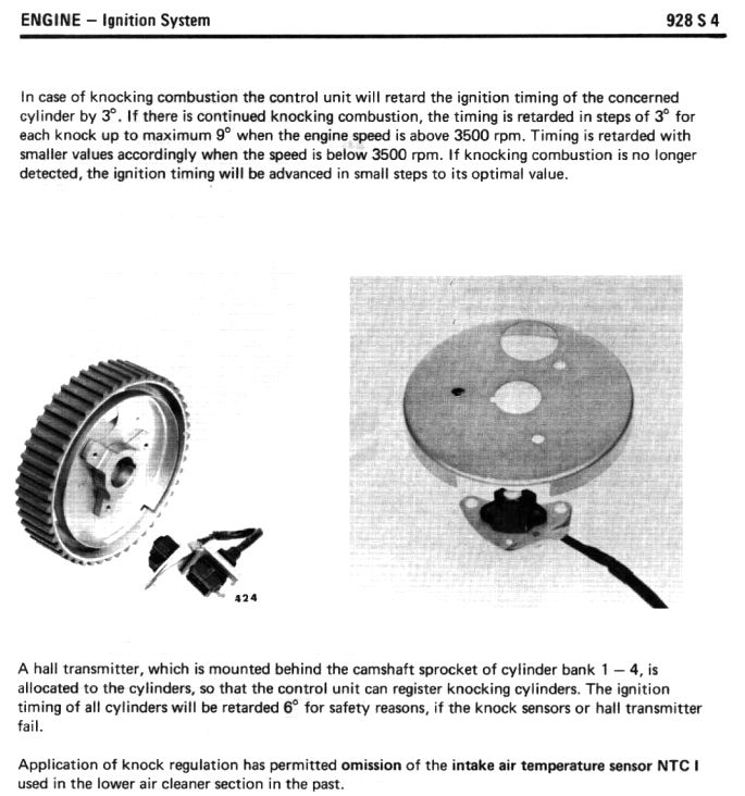
The Hall sensor allows the knock sensors to work. The crank sensor tells the
ECUs where the crank is - on every revolution. This means that the ECU doesn't
know when the cylinders are firing and when they are on exhaust.
The Hall sensor tells the ECUs where one cam is. This enables the ECUs to keep
track of individual firing events.
The ECU calculates cylinder location from waveforms received by both knock
sensors. This allows the EZK ECU to retard ignition on individual cylinders. The
system doesn't work in groups of cylinders.
My understanding is that if the Hall sensor or either knock sensor is faulty,
the entire system dies, and the timing is automatically retarded.
Perhaps one of our ECU experts will correct this if it is wrong.
__________________
Wally Plumley

Cam wheel backing panel with Hall sender opening, front side
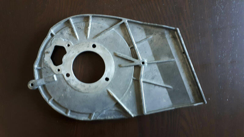
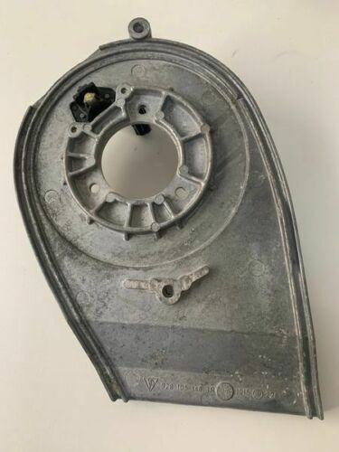
Cam wheel backing panel with Hall sender opening, rear side
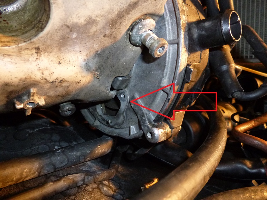
It is not so easy to remove the Hall sensor, but a few special tools do help....
Got it out !!
No... I did not have to remove the lifting eye, it was flexible enough to work
around.....pulled it toward the fender to get the screw out and then pushed it
against the engine slightly twisting it counter clock wise to remove the sensor.
The hook is very soft metal its pretty easy to move it around. The metal is not
spring steel so when you move it ...it stays put. I would assume bending it many
times would cause it weaken.... but that is not required for this task.
You should remove the one spark wire holder ...one 8mm nut and a allen screw.
This is the holder on the valve cover.
You should also remove that 10mm nut on hook holding the wire harness and
grounding the ground wire.
I created a allen wrench by cutting the long part of a allen wrench off and
stuffing it into a 4mm 1/4 inch socket. I attached that to a 12inch
extension....this gave me about 16 inches of extension point straight back.
Avoid using a universal link....it will only cause you problems when turning.
Like I said the vertical hammering on the screw while applying twisting force is
the only way you can get enough break force on the screw if your head are rough
like mine.
Ahh one more detail.... i used a vacuum hose connect to a can of penetrating oil
to clean the grime out of the screws before sticking the allen wrench in the
hole....this will get you a tiny bit more bite on that head. Mine were filled
half filled with grim.
FYI: Feel like I committed a little sin on that hook, figured the hook would get
pulled back and forth if it was actually used for pulling the engine. So the sin
is not as bad as it sounds. Others might not feels the same...


I am un-burying this from an Intake thread I have further down in hopes
someone can help me:
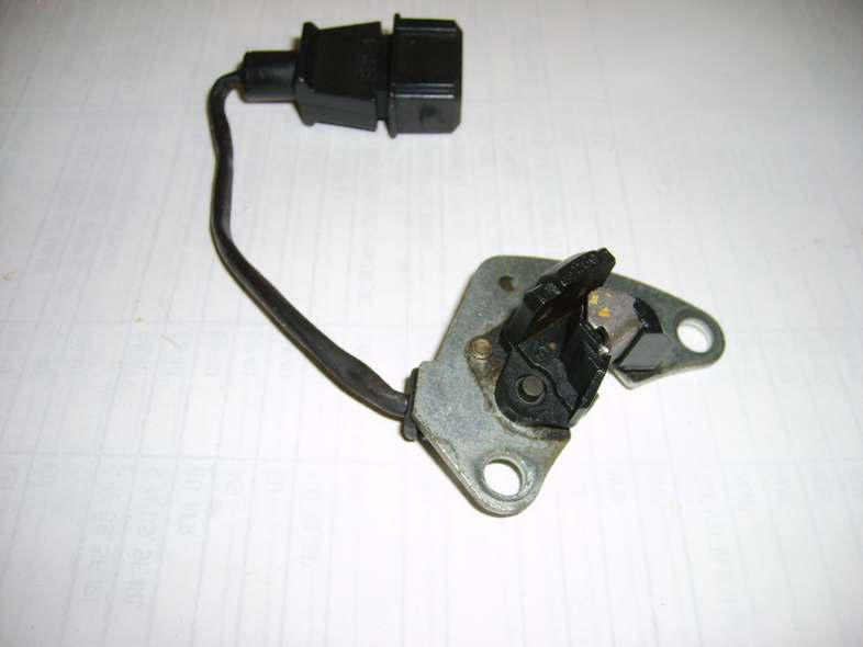
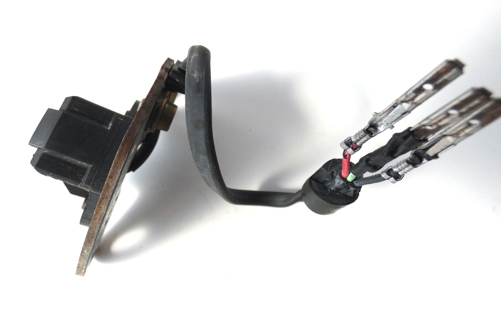
I have a Hall and a Crank Position Sensors whose plastic connectors
disintegrated and I have not taken notes of the wires positions. Now I have new
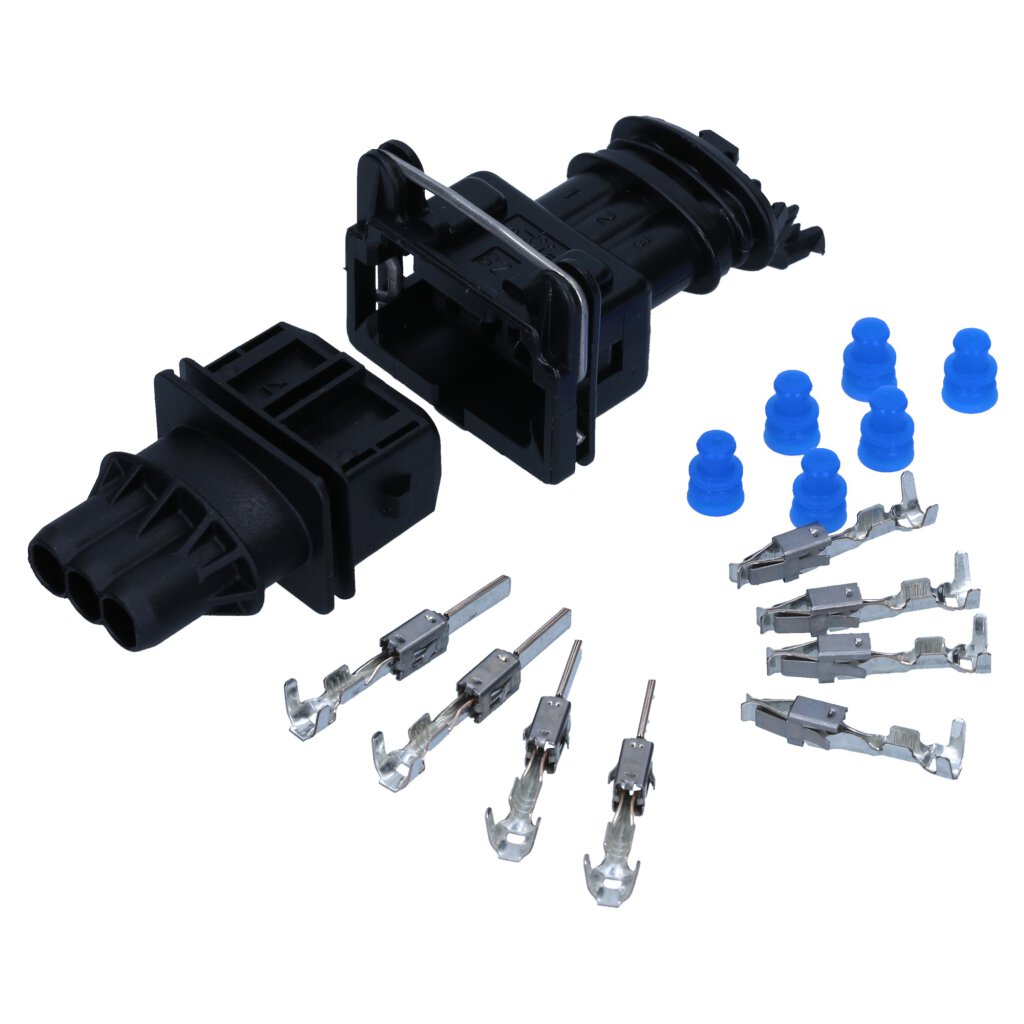
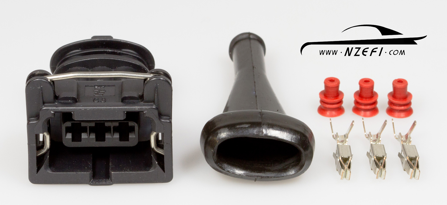
connectors to repair them, but don't know the wires positions.
The connector is asymmetrical. It has two notches on one side (thumb side in the
picture) and one notch on another (indicator finger in the picture)
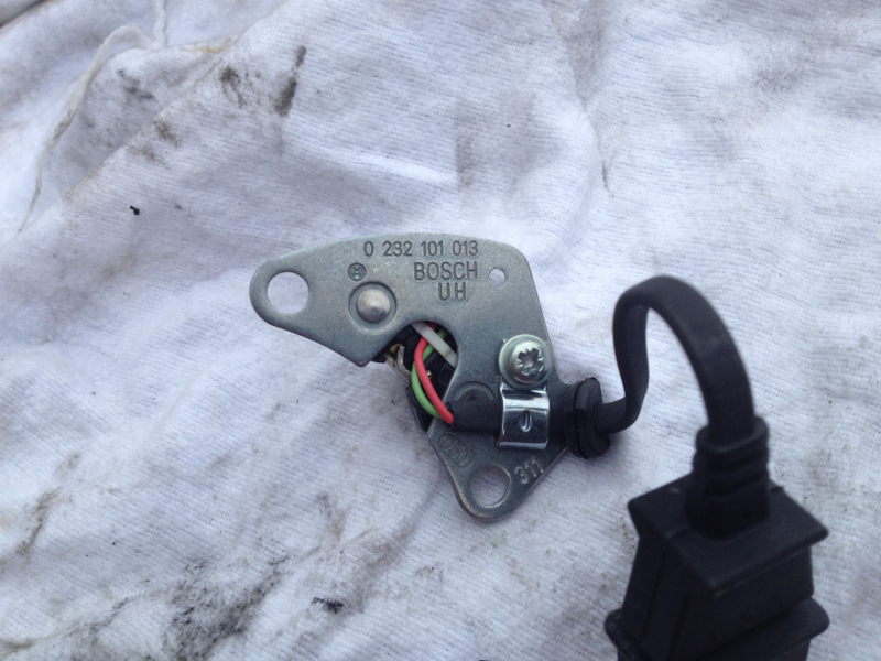
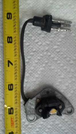
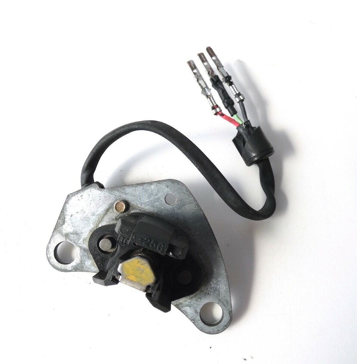
1. Hall Sensor (male) connector. There are three wires coming from sensor:
Black, Green (middle) and Red. Which side I place the Black and which side the
Red. I tried to remove the rubber part of the harness that is in its matching
connector in the car to see the wires color, but it is not coming apart and will
disintegrate if I try.
2. Same question for the Crank Position Sensor. This one has one Black, one
Yellow or Orange (believe this is in the middle) and one thin black or silverish.
Which side to install?
===
CPS wires are Brown, white and the last wire is a screen. Your new connector
might have pin numbers written on it - if so connect white to pin 1, brown to
pin 2, screen to pin 3. If no numbers, the safest course is to buzz from the
cable form connector to pin 23 of EZK for the white, pin 6 for the brown and pin
24 for the screen. Then you will know what wires go where in your new plug
If you bought your 3 pin plug housing from Roger, then it has numbers on - in
the view in your picture pin one is RHS, 2 in the middle, 3 on LH . Look
carefully are the wire end of the connector and you will see the numbers.
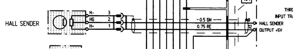
Hall sensor has Red to pin 5 EZK, Green to pin 22 & black (screen) to pin 4.
Unfortunately the circuit diagram doesn't give the plug pin numbers.
JDS
====
John,
Yes, I bought the parts from Roger and I can see the tiny numbers now. Thanks
for the help.
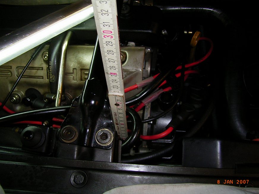
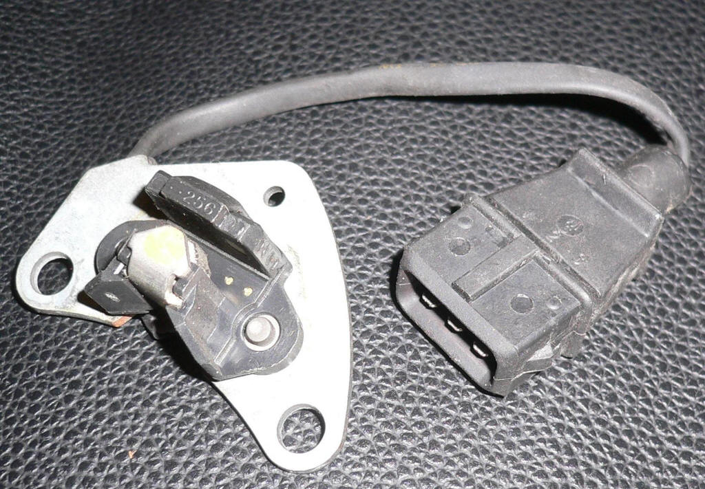
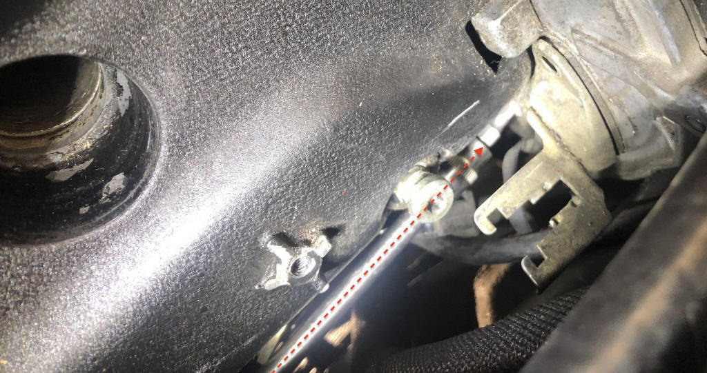
I might be looking at a different sensor; or my car has a sensor wiring that is
not genuine, because the colors do not seem to match (please see pix below). I
am attaching a picture showing the sensor location. It is the black one just
behind the throttle cable pulley and in front of the blue tape. I might be
calling this CPS and it might be something else (?)
But , if this is the CPS but has the wrong wires colors, any hint on how to
place the connectors?
====
in that case white = yellow; Black = brown ; screen is easy...
====
For my 89 I replaced all female connectors (and replaced all sensors).
Looking at the connector from the front and the single notch in the middle is up
and two notches on both sides are down, from left to right the wire colors are:
Knock sensors and impulse sender: black, red, white.
Hall sensor: black, white, red.
Black was what John calls a screen.
====
Well, it's pretty easy
1 > red
2 > green
3 > black
Just as it appears on the print.
====
Can I remove the sensor without taking the engine out?
Yes, it is tricky but you can do it. My suggestion is that you remove the
engine hanger bracket on that side for additional clearance.
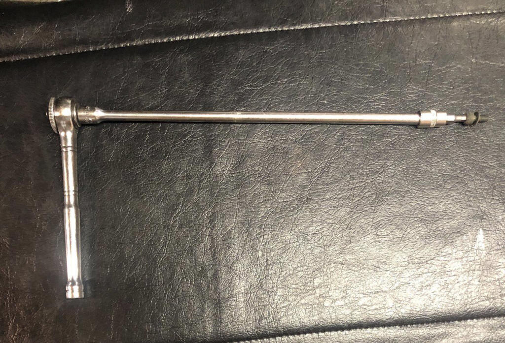
Use a 1/4" allen socket driver and a very long extension like 8"-10". This will
allow you to access the bolts.
This connector is a replacement candidate:
https://www.kabelschuhe-shop.de/KALI-1303-AMP-JPT-set-3-polig-05-10mmA
It takes a bit of adjusting the bracket so that the 6.5mm opening becomes about 7mm.