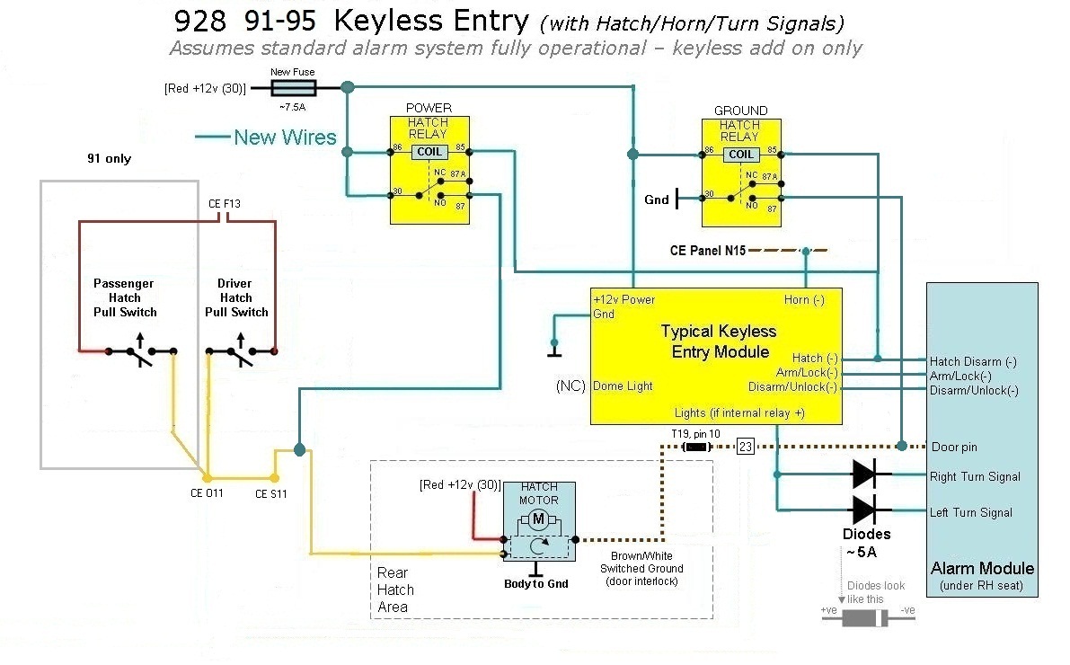
Since lots of keyless entry systems have an internal lighting relay (and
you'd still need 2 more relays)...
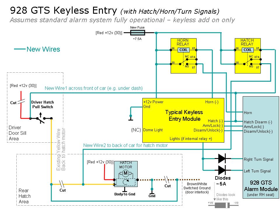
Use the internal relay and 2 diodes to feed each turn signal light circuit. You
can get diodes at radio shack etc - ask for 5A rectifier diodes.
They look a lot like resistors (cylindrical body with a wire exiting each end).
They are polarized devices and only conduct in one direction. You need the
positive ends to go to your relay + output (both of them) and the negative ends
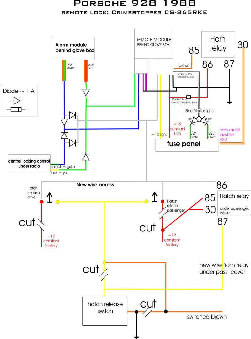
to go to each of the turn signal lines. See Paul's post for examples of diodes
in the circuit - we needed a bunch for his '88 as well as the physical
representation. I prefer diodes over relays - but you have to figure out how to
mount them securely - I recommend to at least solder to wires & encapsulate with
shrink wrap.
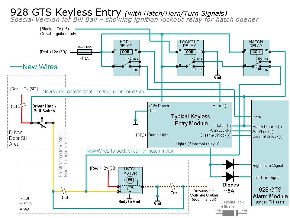
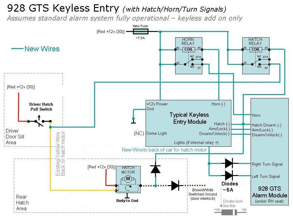
Randy - Here is a diagram for a GTS install - See Andrews post for connection
points on the alarm module...
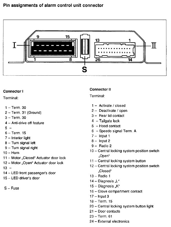
Adding here the translation key back to the Porsche connector names Andrew
posted....
Connector II pin 1 Activate/Closed = Arm/Lock
Connector II pin 2 Deactivate/Open = Disarm/Unlock
Connector II pin 4 Tailgate Lock (eh!) = Hatch Disarm
Connector I Pin 8 Turn Signal Left = Left Turn Signal
Connector I Pin 9 Turn Signal Right = Right Turn Signal
Connector I Pin 10 Horn = Horn
Connector I Pin 1 Term. 30 = +12v battery power (30)
Connector I Pin 2 Term. 31 = Ground (Gnd)
[Connector I Pin 6 Term. 15 = Ignition]
Note that Porsche is very confused calling the Hatch Disable the "Tailgate Lock"
- (tailgate UNLOCK) maybe...
Also if your amp is removed you should have a red 30 & Brown 31 wire for the amp
still there - may be easier than wiring power from the alarm unit....
Alan
----------