Bus structure and pinning naming conventions:
http://www.vintagebus.com/wiring/defs.html
http://www.vintagebus.com/wiring/xref.html
You mean like these?
This is DIN standards stuff. Wally had a handout a bunch of SITMs ago...
jfk
=======
====
Amazingly enough, there's a DIN standard, 72552, that has a number for every
bit of automotive wire terminal they could think of. You can find the numbers at
http://en.wikipedia.org/wiki/DIN_72552
-John-
======
| Terminal | Definition |
|---|---|
| IGNITION | |
| 1 | Ignition coil, ignition distributor, low voltage |
| Ignition distributor with two separate electrical circuits | |
| 1a | to ignition contact breaker I |
| 1b | to ignition contact breaker II |
| 2 | short-circuit terminal (magneto ignition) |
| 4 | Ignition coil, ignition distributor, high voltage |
| Ignition distributor with two separate electrical circuits | |
| 4a | from ignition coil I, terminal 4 |
| 4b | from ignition coil II, terminal 4 |
| 15 | Switched + downstream of
battery (output of ignition/driving switch) |
| 15a | Output at dropping resistor to ignition coil and starter |
| GLOW PLUG AND STARTER SWITCH | |
| 17 | Start |
| 19 | Preheat |
| BATTERY | |
| 30 | input from + battery terminal, direct |
| 30a | input from + terminal of
battery II (12/24 V series-parallel battery switch) |
| 31 | Return line to battery - battery terminal or ground, direct |
| 31b | Return line to negative
battery terminal or ground, via switch or relay (switched negative) |
| (12/24 V series-parallel battery) | |
| 31a | Return line to - terminal of battery II |
| 31c | Return line to - terminal of battery I |
| ELECTRIC MOTORS | |
| 32 | Return line (Polarity reversal possible at terminals 32-33) |
| 33 | Main terminal connection (Polarity reversal possible at terminals 32-33) |
| 33a | Self-parking switch-off |
| 33b | Shunt field |
| 33f | For second lower-speed range |
| 33g | For third lower-speed range |
| 33h | For fourth lower-speed range |
| 33L | Counterclockwise rotation |
| 33R | Clockwise rotation |
| STARTER | |
| 45 | Separate starter relay output; starter input (main current) |
| 45a | Output, starter I Input, starters I and II (Two-starter parallel operation) |
| 45b | Output, starter II (Two-starter parallel operation) |
| 48 | Terminal on starter and on start-repeating relay for monitoring starting procedure |
| TURN SIGNAL FLASHER | |
| 49 | Input |
| 49a | Output |
| 49b | Output, second turn-signal circuit |
| 49c | Output, third turn-signal circuit |
| STARTER | |
| 50 | Starter control (direct) |
| 50a | Output for starter control (Series-parallel battery switch) |
| 50b | Starter control with parallel operation of two starters with sequential control |
| 50c | Input at starting relay for
starter I (Starting relay for sequential control of the engagement current during parallel operation of two starters) |
| 50d | Input at starting relay for
starter I (Starting relay for sequential control of the engagement current during parallel operation of two starters) |
| 50e | Input, Start-locking relay |
| 50f | Output, Start-locking relay |
| 50g | Input, Start-repeating relay |
| 50h | Output, Start-repeating relay |
| ALTERNATOR | |
| 51 | DC voltage at rectifier |
| 51e | DC voltage at rectifier with choke coil for daytime driving |
| TRAILER SIGNALS | |
| 52 | Signals from trailer to towing vehicle, general |
| WIPER MOTOR | |
| 53 | Wiper motor, input (+) |
| 53a | Wiper (+), self-parking switch-off |
| 53b | Wiper (shunt winding) |
| 53c | Electric windshield-washer pump |
| 53e | Wiper (brake winding) |
| 53i | Wiper motor with permanent magnet and third brush (for higher speed) |
| TRAILER SIGNAL | |
| 54 | For lamp combinations and trailer plug connections |
| TRAILER STOP LAMP | |
| 54g | Pneumatic valve for additional retarding brake, electromagnetically actuated |
| LIGHTING | |
| 55 | Fog lamps |
| 56 | Headlamp |
| 56a | High beam, high-beam indicator lamp |
| 56b | Low beam |
| 56d | Headlamp-flasher contact |
| 57 | Side-marker lamp: motorcycles, mopeds. Abroad also cars, trucks, etc. |
| 57a | Parking lamp |
| 57L | Parking lamp, left |
| 57R | Parking lamp, right |
| 58 | Side-marker lamps, tail lamps, license-plate lamps and instrument-panel lamps |
| 58b | Tail-lamp changeover for single-axle tractors |
| 58c | Trailer plug-and-receptacle assembly for single-conductor tail-lamp cable with fuse in trailer |
| 58d | Variable-intensity instrument-panel lamp, tail-lamp and side-marker lamp |
| 58L | Side-marker lamp, left |
| 58R | Side-marker lamp, right; license-plate lamp |
| ALTERNATOR (magneto, generator) | |
| 59 | AC voltage, output, rectifier, input |
| 59a | Charging armature, output |
| 59b | Tail-lamp armature, output |
| 59c | Stop-lamp armature, output |
| 61 | Alternator charge-indicator lamp |
| TONE-SEQUENCE CONTROL DEVICE | |
| 71 | Input |
| 71a | Output to horns 1 & 2, low |
| 71b | Output to horns 1 & 2, high |
| 72 | Alarm switch (rotating beacon) |
| INTERIOR | |
| 75 | Radio, cigarette lighter |
| 76 | Speaker |
| 77 | Door-valve control/td> |
| SWITCHES | |
| Break-contact and changeover switches | |
| 81 | Input |
| 81a | 1st output, break side |
| 81b | 2nd output, break side |
| Make-contact switches | |
| 82 | Input |
| 82a | 1st output |
| 82b | 2nd output |
| 82z | 1st input |
| 82y | 2nd input |
| Multiple-position switches | |
| 83 | Input |
| 83a | Output, position 1 |
| 83b | Output, position 2 |
| 83L | Output, left-hand position |
| 83R | Output, right-hand position |
| CURRENT RELAY | |
| 84 | Input, actuator and relay contact |
| 84a | Output, actuator |
| 84b | Output, relay contact |
| SWITCHING RELAY | |
| 85 | Output, actuator (end of winding to ground or negative) |
| 86 | Start of winding |
| 86a | Start of winding or 1st winding |
| 86b | Winding tap or 2nd winding |
| Relay contact for break and changeover contacts | |
| 87 | Input |
| 87a | 1st output (break side) |
| 87b | 2nd output |
| 87c | 3rd output |
| 87z | 1st input |
| 87y | 2nd input |
| 87x | 3rd input |
| Relay contact for make contact | |
| 88 | Input |
| Relay contact for make and changeover contacts (make side) | |
| 88a | 1st output |
| 88b | 2nd output |
| 88c | 3rd output |
| Relay contact for make contact | |
| 88z | 1st input |
| 88y | 2nd input |
| 88x | 3rd input |
| ALTERNATOR and
VOLTAGE REGULATOR GENERATOR and GENERATOR REGULATOR |
|
| B+ | Battery positive |
| B- | Battery negative |
| D+ | Dynamo postive |
| D- | Dynamo negative |
| DF | Dynamo field |
| DF1 | Dynamo field 1 |
| DF2 | Dynamo field 2 |
| Alternator with separate rectifier | |
| J | Excitation winding positive |
| K | Excitation winding negative |
| Mp | Center point terminal |
| U,V,W | Alternator terminals |
| DIRECTION INDICATOR (turn-signal flasher) | |
| C | First indicator lamp |
| C0 | Main terminal connection for separate indicator circuits actuated by the turn-signal switch |
| C2 | Second indicator lamp |
| C3 | Third indicator lamp (e.g., when towing two trailers) |
| L | Turn-signal lamps, left |
| R | Turn-signal lamps, right |
| OLD | NEW |
|---|---|
| 1 | 1, 53(wiper), 53e |
| 2 | 2, 53e |
| 3 | 53, 53b(wiper) |
| 4 | 4, 53a, 53b(wiper) |
| 15 | 15, 49(turn-signal flasher) |
| 15+ | 49 |
| 15/54 | 15, 49, 54 |
| 16 | 15a, 15 |
| 30 | 30, 33(motor) |
| 30/51 | 30, 87, 88(relay) |
| 30f | 45 |
| 30h | 45, 45a |
| 30h I | 45a |
| 30h II | 45b |
| 30L | 33L (motors) |
| 30R | 33R (motors) |
| 31 | 31, 31c, 32(motors) |
| 31a | 31a, 31c |
| 31B- | B- |
| 50 | 50, 50b, 50f, 50h |
| 50a | 50, 50a, 50e, 50g |
| 50b | 50d |
| 50k | 50d |
| 50 II | 50c |
| 51 | 51, 59, B+ |
| 51 - | 59 |
| 51a | 59 |
| 51B+ | B+ |
| 54 | 54, 53a, 54g |
| 54/15 | 15 |
| 54d | 53(wiper) |
| 54e | 33b, 53b(wiper) |
| 54L | 49a |
| 58 | 58, 58L, 58R |
| 58b | 58b, 58d |
| 59 | 59a |
| 85d | 31b(alarm switch) |
| B+30 | B+ |
| B+51 | B+ |
| D+/61 | D+ |
| D-/61 | D- |
| H | 71 |
| HL | L (L54b) |
| HR | R (R54b) |
| K | C |
| K0 | C0 |
| K1 | C, C2 |
| K2 | C2 |
| K3 | C2, C3 |
| K4 | C2, C3 |
| L54 | L (L54) |
| N | 55 |
| P | C, 57a |
| PL | 57L |
| PR | 57R |
| R | R, 75 |
| R54 | R, (R54) |
| R54b | Rb |
| S | 49a, 53(wiper) |
| S4 | 49a |
| SBL | (L54) |
| SBR | (R54) |
| VL | L |
| VR | R |
| + | 15, 49(turn-signal flasher) |
| 53, 53a(wiper) | |
| +2 | 53a |
| +15 | 49 |
| -1 (ignition coil), 31 |
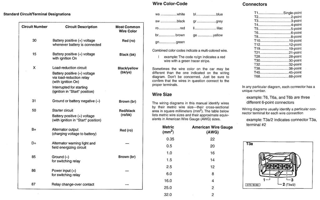
You failed to mention color coding. 30 is red while 15 is red with a white
stripe. Black can also be ignition on as well. And of course the most common
color confusion for the average American is the German use of Brown as ground.
Brown with white then becomes a temporary ground as with the dome light
switches. Grey is usually used for lights.
Dan the Pod Guy
Portia's Parts
===========
One more, but now in German, lifted from a standards website: