At 08:22 AM 6/16/2004, D. Overington Consulting wrote:
I have a 1990 S4 (in Australia) and I've now had it for about 3 months.
It has two problems.
Occasionally the engine loses almost all power and idles roughly. To get it going I simply shut it down for 30 secs and start it up and it runs fine until next time (any time between 100 feet and 500 miles). I have put new main and in-tank fuel pumps in it, thinking that may have been the problem. Problem has never occurred whilst under load uphill, but always when pulling away gently after a gradual descent. No errors
etc showing up on hammer.
===
The late model cars have an ignition monitoring system to prevent cat fires. If
one ignition system dies, an exhaust temp sensor reports low temp, and the
monitoring system kills the injection on those four cylinders. It is not too
unusual for the temp sensors to eventually malfunction.
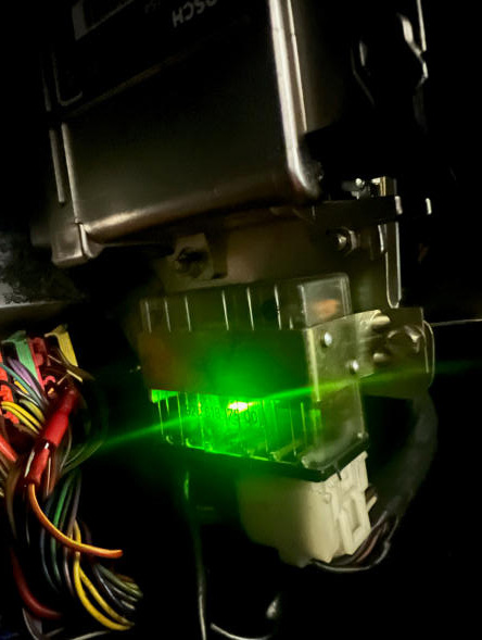
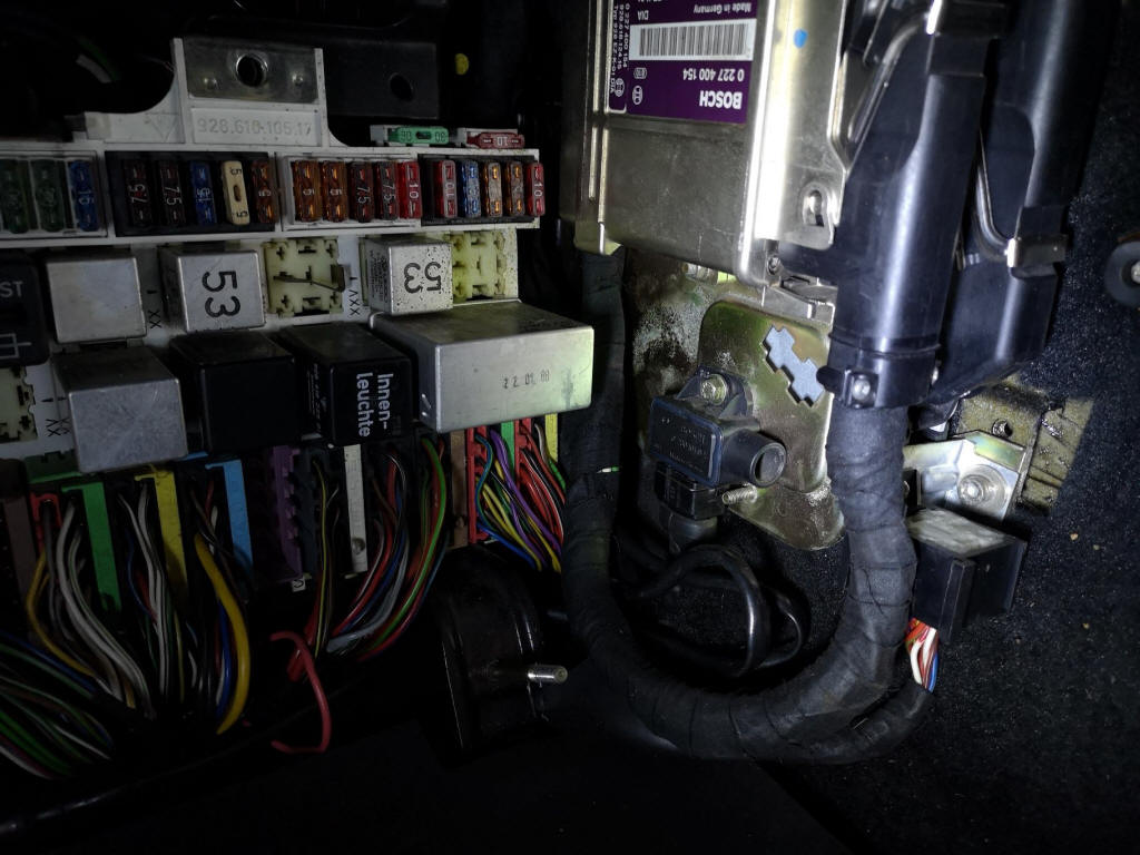
Remove the ECU cover, and find the monitoring relay, a clear plastic box.
When the engine loses power, check the box for an illuminated red or green LED.
Here is the text of a Service Bulletin:
9203
Subject:
Diagnosing Ignition Monitoring System
ATTENTION:
Service Manager/Service Technician
Models Affected:
928 S4/GT/GTS
>From 1989 Models ->
Concern:
Checking of components after activation of the ignition monitoring system
(injection circuit switched off fault codes 1131 of 1231).
Activation may be caused by the following:
- Damaged or defective exhaust gas temperature sensors.
- Possible damage to the ignition coil wire left side (in driving direction)
between the ignition coil and distributor cap.
- Poor grounding of the mounting plate for the ignition final stages.
- Poor physical connection of the electrical plugs on the ignition final stages.
Parts Information:
New version temperature sensor Part Number 928 606 155 02 New coil wire with
hose covering Part Number 928 602 040 01 (for left side) Repair Information:
1.
Check the left side ignition coil wire. Be certain the coil wire is routed
freely and not under tension. If damaged, replace with new version (see parts
information).
2. Check all ignition components and connectors for corrosion, tightness, correct connection and damage. Repair or replace as necessary. If an ignition circuit has malfunctioned, an LED indication will be given by the ignition monitor relay located on the L-H control unit mounting plate. Ignition circuit I (cyl. 1-7-6-4) Red LED Ignition circuit II (cyl. 3-2-5-8) Green LED

3. Before replacing temperature sensors, check the voltage
difference of both temperature sensors as per step 4 of this bulletin. Sensors
are located in the exhaust ports:
Model '89-'90, cyl. 4 and 8
Model '91 cyl. 3 and 7
The function of the ignition circuits and light diodes located in the ignition
monitor relay remains unchanged. It is not possible to determine from the LED
display of the ignition monitor relay if one or both temperature sensors are
defective or which temperature sensor has failed.
When installing temperature sensors, coat the sensor adapter threads with
molykote paste HTP (white) and torque sensors to 10 N-m.
4. The voltage difference of the temperature sensors must be checked in order to
ensure proper operation of the ignition monitor system.
Checking sensor voltage difference:
- Start engine and bring to operating temperature.
- Loosen the mounting bolt for the ignition monitor relay and pivot the relay up
to gain access to the plug terminals Do not disconnect the relay plug.
- Set volt meter to the millivolt range and connect leads between E1 and E2 of
ignition monitor relay (Figure 3, white wires). A digital volt meter must be
used. Polarity is not important.
- Measure voltage with the engine idling and again at approximately 2000 RPM. A
maximum difference of +2.5 mV or -2.5 mV (depending on polarity) is permitted.
If the voltage difference is above 2.5 mV, stop the engine, loosen and rotate
one temperature sensor. Retighten sensor and check voltage difference. If the
difference is above 2.5 mV, stop the engine and rotate the other sensor. If
after rotating the sensors to different positions, the voltage difference is too
high (above 2.5 mV) the temperature sensors are defective and must be replaced.
*****
>2. Sometimes it runs hot, with the temp. needle going well towards the high / red mark. I believe the front louvres are opening and closing properly. Am putting a new thermostat in tomorrow, just to do the easy things first.
>I am tempted to think the two are related, something along the lines that the engine is getting hot, so partly shutting itself down / retarding ignition. But this is just my musings with no scientific basis.
>If anyone out there is able to point me in the right direction, for me to suggest to the Porsche workshop, I'd be very grateful. (I've also posted a similar plea for help on the Landsharkoz website. Hi Jaime!!)
The most common problem is a temp gauge that reads high. A hot engine will feel
and smell hotter than normal.
There are numerous things that can cause a temp increase, including an air
bubble in the cooling system, sticking thermostat, bad fan control or fan motor,
etc. But again, the first thing to determine is if the engine is actually
overheating.
Wally Plumley
928 Specialists
www.928gt.com
==========
A few weeks back someone on the list mentioned how to cross wire the four
cylinder mode relay so all cylinders will run. I have this problem and need
to get the car running for a while to run some tests and move the car.
Thanks for any help and please send me a copy directly.
Thanks
Dan the Pod Guy
Portia's Parts
==========
Dan,
bridge connections 2, 4 and 5 in the IMR relay socket/connector.
Cheers
Graham
=========
Most likely one of the Ignition Monitoring temp probes is bad. You can
replace the sensor ($$$) or since you don't have cats just bypass that system
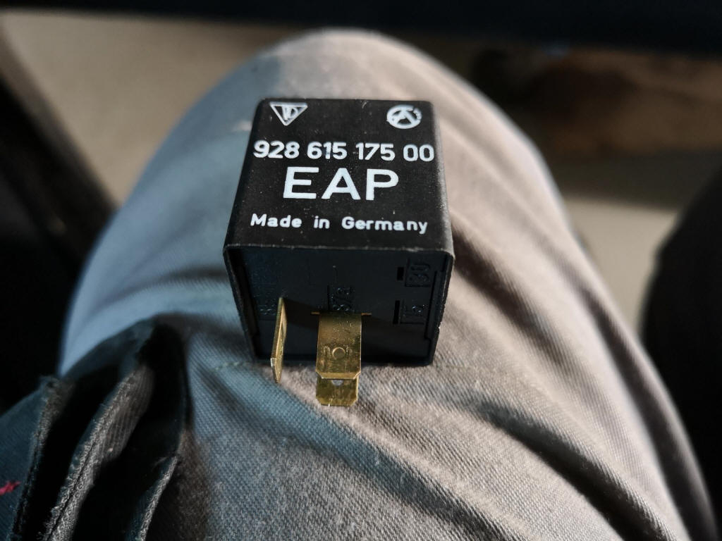
with a Bypass relay. Part # is 928.615.175.00 and we have them on the website
for $15.23. I recommend every 89 and later owner to have one in their glove box
for when that system starts acting up. In a pinch you can also remove the relay
(large clear relay on engine computer console) and jumper pins 2,4,5 together on
the relay socket (leave relay out) which should put you back in to 8 cylinder
mode.
David Roberts
928 SPECIALISTS
========
wsm page28-77 I think. Also be aware that the LH ecu is able to register an activation of the monitoring circuit it seems....
=======
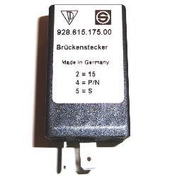
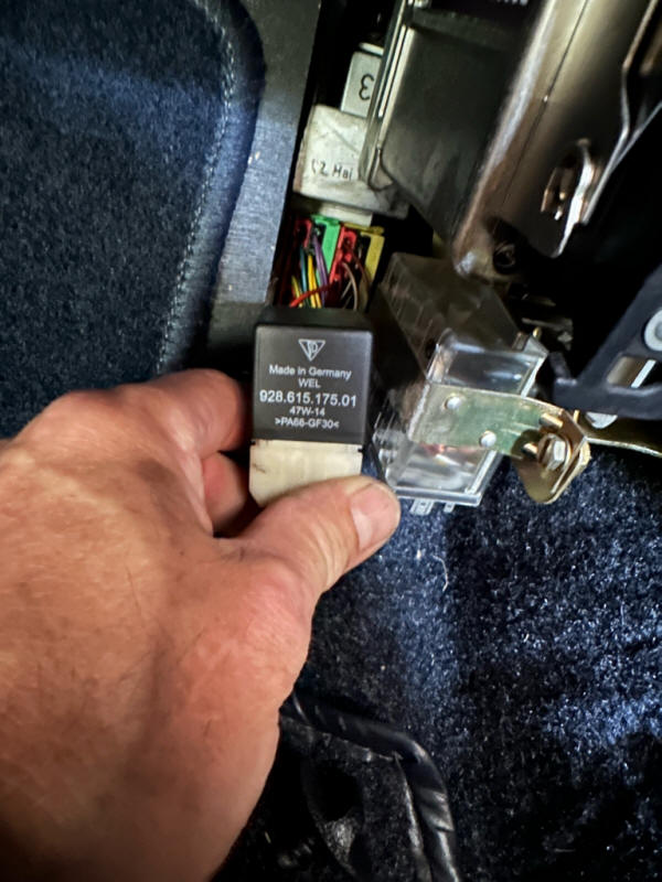
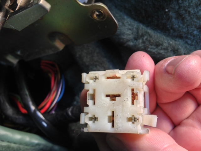
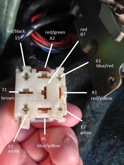
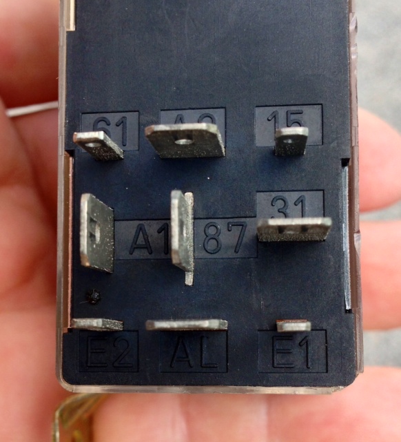
Basically connect on the connector: 87 with A1 and A2.
87 is 12v supply, A1 is power to injectors 1,4,6,7 and A2 provides power to injectors 2,3,5,8
--------
The running on 4 cylinders is NOT LIMP HOME MODE !! It is get it off the freeway out of the intersection. LIMP HOME is a default program for when the mass air takes a dump BUT The car still runs on all 8 cylinders at very low power ! When the ignition monitor relay the one with the red green lights THINKS that 1/2 of the ignition system is having a failure and two cylinders on each bank may be pumping fuel and air into the catalytic converter IT shuts down the injection to those 4 cylinders (2 on each bank) which are showing low exhaust temperatures as measured on cylinders 4 and 8 for 1989 and 3 and 7 1990
The purpose is to keep people from trying to make it home on 4 cylinders and burn their car up in the process.
Jim Bailey
====
The Ignition Circuit Monitoring Relay
The 928 S4 and newer engines have two separate ignition circuits. Ignition
circuit ONE is comprised of cylinders 1, 4, 6, 7, the right side coil and
distributor. Ignition circuit TWO is comprised of cylinders 2, 3, 5, 8, the left
side coil and distributor.
If there is a failure in one of the ignition circuits, raw fuel is pumped out of
the cylinders and into the exhaust system.
When the raw fuel hits the hot catalytic converters a fire may occur – OUCH!
From model year 1989 onwards, Porsche added the Ignition Circuit Monitoring
Relay as a safety feature. This circuit is completely independent of the LH
injection system. It is identified in the workshop manual wiring diagram as the
Ignition Control Circuit. The function of the system is to turn off the fuel
injection to the failing ignition circuit.
The inputs to the relay are two exhaust temperature sensors that provide input
to the relay. If one of the ignition circuits fails, the “Ignition Circuit
Monitoring Relay” shuts off the pulse signal to all of the fuel injectors of the
affected circuit.
As you might imagine, the symptoms of a shut down ignition circuit are a
significant reduction in power and a rough running engine. For trouble shooting,
you need to determine if the shut-down is due to a failed ignition circuit or a
failure of the Ignition Circuit Monitoring Relay itself.
The first step is to quickly identify which circuit is affected. Look at the
clear relay module that is fitted next to the EZK spark control unit in the
passenger compartment.
When ignition circuit ONE (cylinders 1, 4, 6 & 7) is shut-down, a RED LED is
illuminated.
When ignition circuit TWO (cylinders 2, 3, 5 & 8) is shut-down, a GREEN LED is
illuminated.
Check the ignition circuits and repair as necessary. If no problem is found with
the ignition circuit, there may be a failure of the Ignition Circuit Monitoring
Relay circuit, the signals to test are:
1. Terminal 31: ground
2. Ground must be present at terminal AL when the ignition switch is in the off
position.
3. Battery voltage must be present at terminals A1, A2, 15 and 87 when the
ignition is in the on position.
4. Battery voltage must be present at terminals AL and 61 when the engine is
running.
5. A Voltage value of approximately 2.7v must be present at both terminals E1
and E2 when the ignition is in the on position.
6. The resistance between E1 and E1 is approximately 5 – 10 Ohms (measured at
the disconnected relay socket).
The temperature sensors that fit in the exhaust system should also be inspected.
A more detailed explanation is provided in the factory workshop manuals.
If you desire further information please contact me.
Rich Andrade
www.electronikrepair.com