Pages from Service Info Tech 1989-1994.pdf
Part II: The Ignition Circuit Monitoring Relay
The 928 S4 and newer engines have two separate ignition circuits. Ignition
circuit 1 is comprised of cylinders 1,4,6,7, the right side coil and
distributor. Ignition circuit 2 is comprised of cylinders 2,3,5,8, the left side
coil and distributor. If there is a failure in one of the ignition circuits, raw
fuel is pumped out of the cylinders and into the exhaust system. When the raw
fuel hits the hot catalytic converters a fire may occur – OUCH!
From model year 1989 onwards, Porsche added the Ignition Circuit Monitoring
Relay as a safety feature. This circuit is completely independent of the LH
injection system. It is identified in the workshop manual wiring diagram as the
Ignition Control Circuit. The function of the system is to turn off the fuel
injection to the failing ignition circuit. The inputs to the relay are two
exhaust temperature sensors that provide input to the relay. If one of the
ignition circuits fails, the “Ignition Circuit Monitoring Relay” shuts off the
pulse signal to all of the fuel injectors of the affected circuit.
As you might imagine, the symptoms of a shut down ignition circuit are a
significant reduction in power and a rough running engine. For trouble shooting,
you need to determine if the shut-down is due to a failed ignition circuit or a
failure of the Ignition Circuit Monitoring Relay itself.
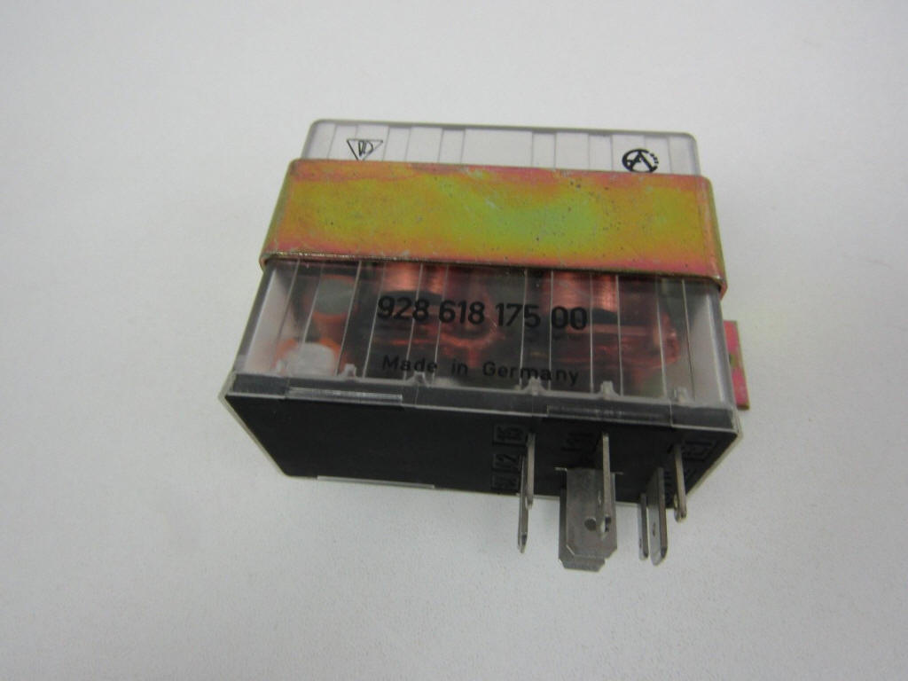
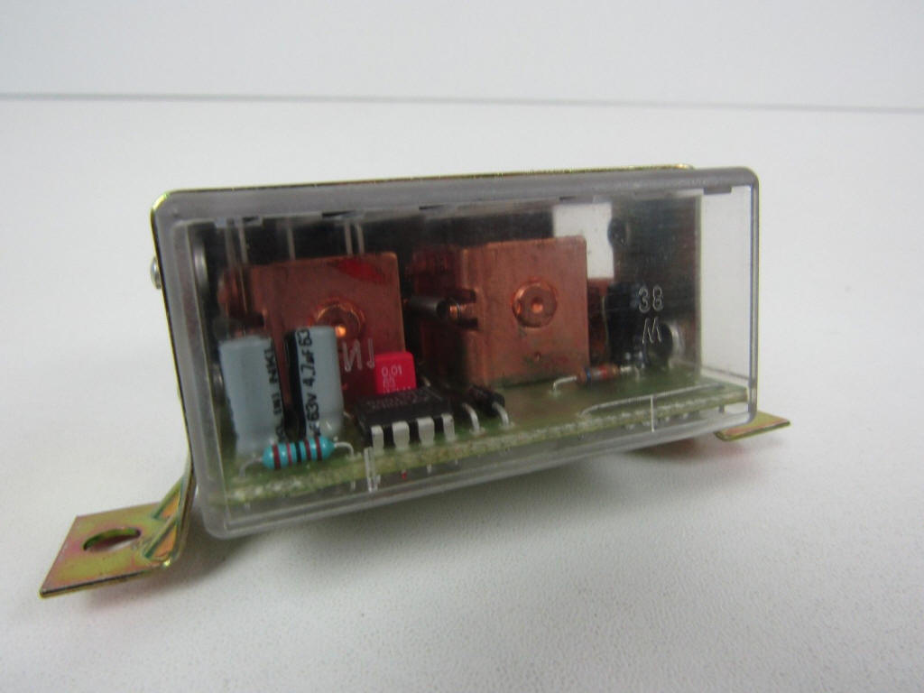
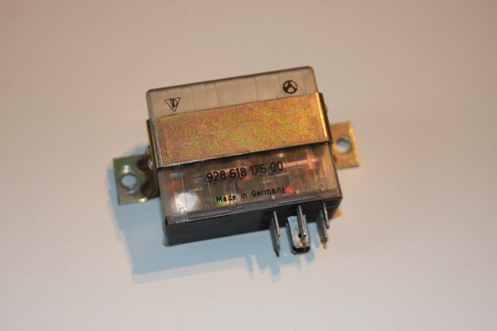
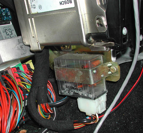
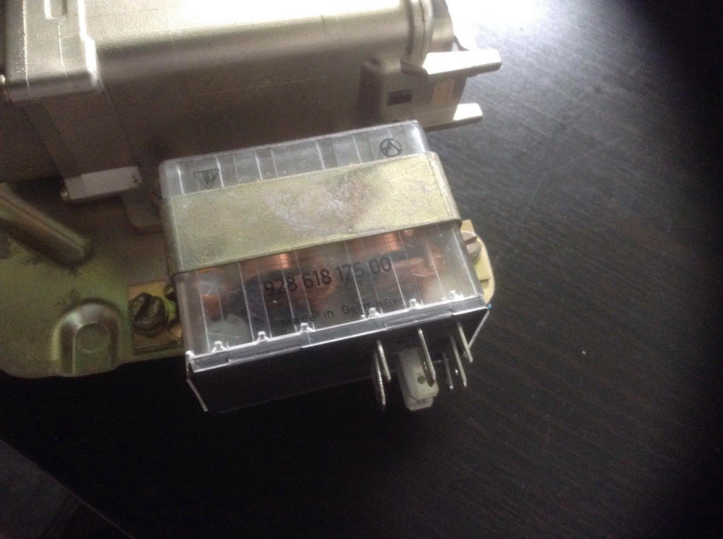
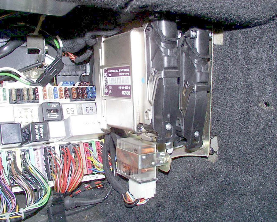
The first step is to quickly identify which circuit is affected. Look at the
clear relay module that is fitted next to the EZK spark control unit in the
passenger compartment.
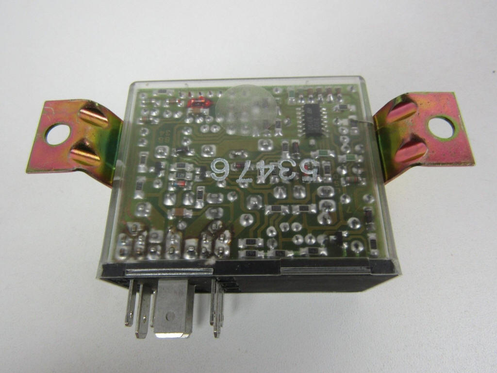
When ignition circuit 1 (cylinders 1,4,6,7) is shut-down, a red LED is
illuminated.
When ignition circuit 2 (cylinders 2,3,5,8) is shut-down, a green LED is
illuminated.
Check the ignition circuits and repair as necessary. If no problem is found with
the ignition circuit, there may be a failure of the Ignition Circuit Monitoring
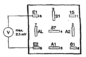
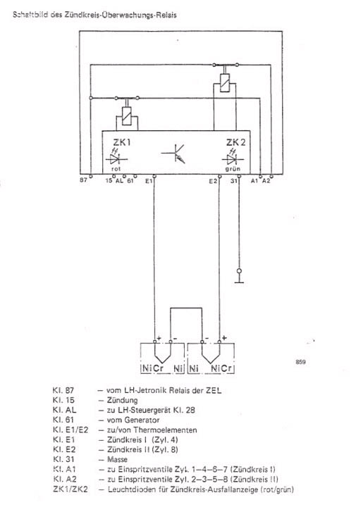
Relay circuit, the signals to test are:
1. Terminal 31: ground
2. Ground must be present at terminal AL when the ignition switch is in the off
position.
3. Battery voltage must be present at terminals A1, A2, 15 and 87 when the
ignition is in the on position.
4. Battery voltage must be present at terminal 61 when the engine is
running.
5. AL outputs a voltage signaling the
LH that the IMR is in normal operation (no faults to be logged).
6. A Voltage value of approximately 2.7 V must be present at both terminals E1
and E2 when the ignition is in the on position. *note: I
don't think this is correct. You should see almost 0mV when the engine is warm
and running. The temp sensors should supply about 2.5mV but they are connected
in reverse polarity so that +2.5mV and -2.5mV result in 0mV difference.
7. The resistance between E1 and E1 is approximately 5 – 10 Ohms (measured at
the disconnected relay socket). This is the resistance or two sensors in series.
The temperature sensors that fit in the exhaust system should also be inspected.
A more detailed explanation is provided in the factory workshop manuals.
Rich Andrade (some adjustments by Theo Jenniskens)
Special Features of ignition Circuit Monitoring Relay
Since the four cylinders still draw in air after switching off the injection
circuit, the oxygen sensor would recognize excessive air and regulate the
air/fuel mixture of the perfect condition cylinders in rich direction. Oxygen
sensor control is switched off together with switching off the ignition circuit,
in order to prevent this.
Terminal 15 of the relay has voltage via CEL when turning on the ignition.
Terminal AL of the relay (this wire leads to LH control unit term. 28) has
ground with “ignition on”.
With “ignition on” the LH control unit will be coded for operation without
catalytic converter via term. AL of the relay, since the coding, whether with or
without catalytic converter, for the LH control unit is accomplished via
positive or ground on term. 28 of the LH control unit.
If the engine is started and term. 61 of the relay has alternator voltage,
voltage is supplied to term. AL and the LH control unit is therefore coded for
operation “with catalytic converter”.
If an ignition circuit would now fail and the pertinent relay contact opens.
Ground would be applied on term. AL and the LH control unit switches over to
operation “without catalytic converter”.
Since, however, in cars without catalytic converter idle speed CO level
adjustments are made via a potentiometer and this potentiometer on the other
hand is not installed in cars with catalytic converter (adaptive oxygen sensor
control), a 150 ohm resistor integrated in the coding plug of the LH or EZK
control unit sends a fixed value (replacement value) to the LH control unit for
guarantee of engine idling when the ignition circuit monitoring relay switches
and therefore oxygen sensor control is switched over to control without oxygen
sensor.
Delayed Switching
The relay is inoperative for about 18 seconds after each engine start, in order
to prevent unwanted switching of the ignition circuit monitoring relay due to
non-uniform cooling of a stopped engine There must also be a difference in
voltage of > 6 mV on connections El and E2 for at least 2.5 seconds before
activation of the relay.
Self-monitor
Great differences in voltage on connections El and E2 are recognized as faults
on the thermo elements or their power supplying leads by a circuit integrated in
the ignition circuit monitoring relay. This always causes switching off of fuel
injection circuit for ignition circuit I or II and activation of the green or
red light
emitting diode. Resistance can be measured on connections El and E2 of a
disconnected relay plug with an ohmmeter to check the thermo elements and power
supplying leads.
Approx. 5 to 10 ohms between El and E2 for perfect condition thermo elements and
leads.
Ohmmeter displays open (-ohms) in case of a fault.
---------
Well, I'm confused now.
The ignition monitoring relay (the one with a green and a red LED) monitors
exhaust temperature. I assume it does this to discover if
unburned fuel possibly are getting into the exhausts, which means it could enter
the cats, causing expensive damage.
In such a situation it then shuts off that bank (by cutting fuel).
This is what I have believed. However, Wally Plumley stated that the system does
not work this way. The ignition monitoring relay actually
shuts off four cylinders, but based on which ignition circuit they are in. This
makes sense, since they LEDs of the monitoring relay are
connected to which ignition circuit is bad. But this means that you will not
know where the problem is, if you just monitor exhaust temps, since both
ignition circuits contribute to both exhaust sensors.
So. How do this work? Will the ignition monitoring relay shut down four
cylinders (two in each bank), or shut down one whole bank?
Johnny
------
Johnny,
One sensor picks up from one side indicating the 3 temp and the other on the 7
cylinder. It responds if one is low temp compared to the other one. This results
in activating of the relay and shutting down one set of injectors. The injectors
are wired identical to the ignition, so not 1234 and 5678 but 1467 and 2358. So
shutting down fuel supply to one set is matched to failure of that ignition
circuit.
In the 89 and 90 models, the sensor was at the 4 and 8 cylinder, but this
changed in 1991 to the 3 and 7 cylinder. Yes, the other cylinders also
contribute but apparently not so much that it is not able to tell which is
failing (less heat). It seems that Porsche changed their mind in 1991, maybe
because of unjustified activation. Not sure, just guessing.
IMR -> Green LED = Driver side problems, Red LED = Passenger side problems.
regards
Theo
1992 928gts Midnight Blue (2006-)
1988 928s4 Cherry Red (1999-2006)
The Netherlands
http://jenniskens.livedsl.nl
http://928gts.jenniskens.eu
-------
Theo has explained it well, so this is a bit redundant...
The late 928s have two virtually independent ignition systems. There were
sufficient cases of failure of one of these ignition systems, followed by
overheated cats leading to serious fires, to convince Porsche that Something Had
To Be Done. That Something was the Ignition Monitoring System. The exhaust temp
sensors of that system measure the EGTs of two cylinders - one on each ignition
system. If the EGTs of the two cylinders become different enough, the Ignition
Monitoring System relay kills the fuel injectors feeding the four cylinders
fired by the ignition system including the cylinder with the cold exhaust.
The key is that the Ignition Monitoring System monitors the EGTs (Exhaust Gas
Temperatures) of two individual cylinders, not the EGTs of the left and right
banks. The fuel injectors were divided into two sets of four, matching the
arrangement of the ignition systems. All injectors still batch fire at once, but
they are fired by two different sets of wires contained in the single injection
harness.
Wally Plumley
928 Specialists
www.928gt.com
=========
Here is Porsche's official IMR check procedure:
Ignition monitoring diagnosing.pdf