

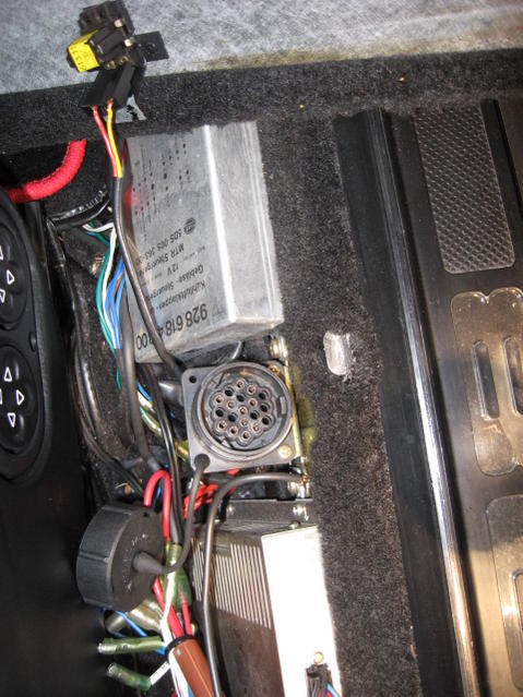
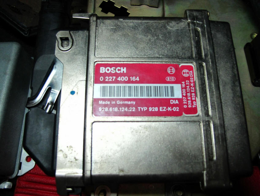
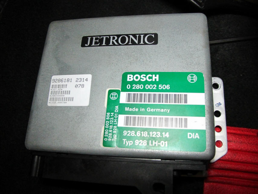
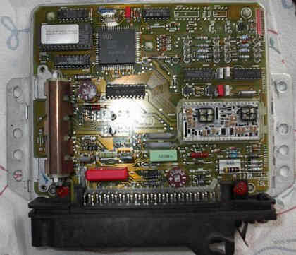
The 928s4 uses a LH 2.3 which is very similar as you can see.

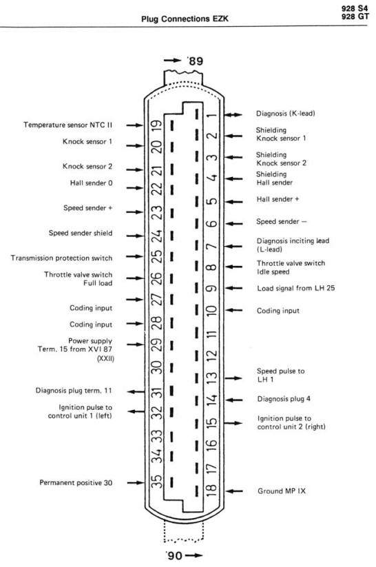
Yellow: Ignition: EZK ecu Red: Injection:LH2.3 ecu
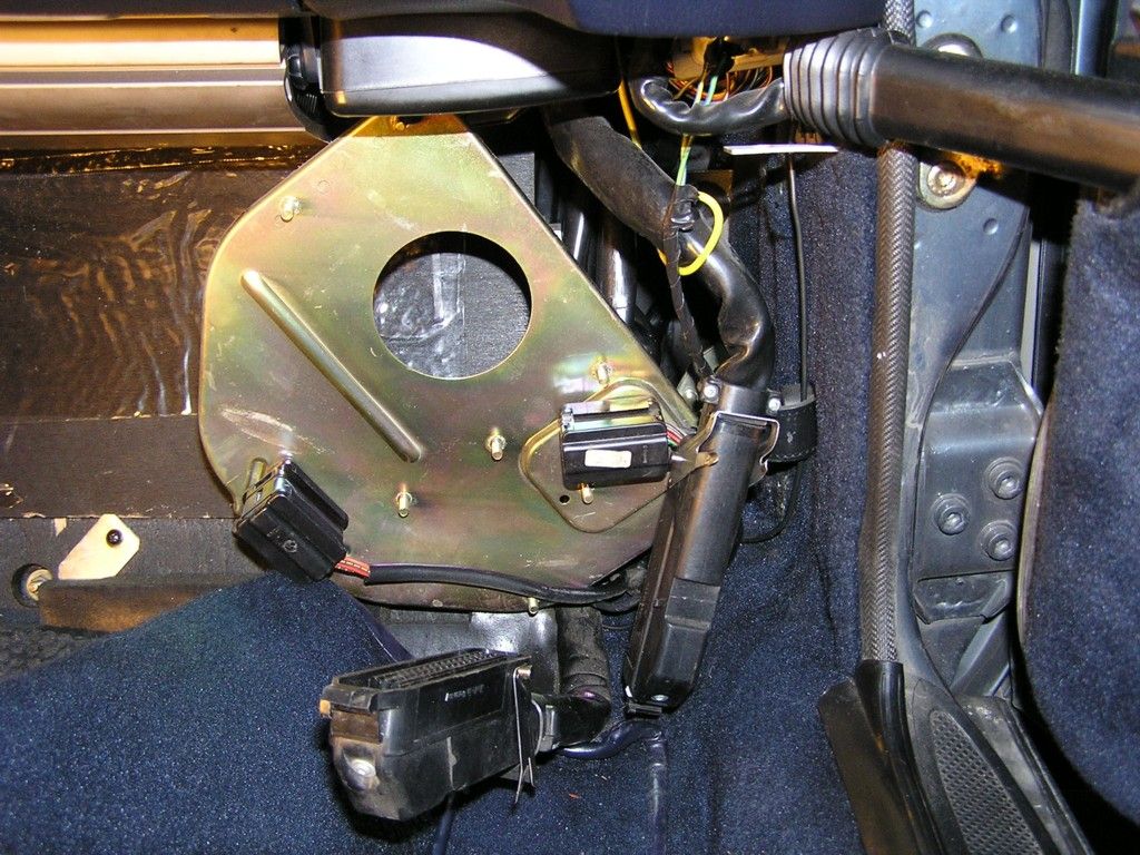
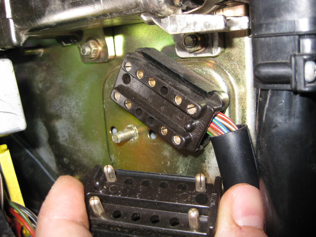
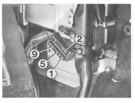
The next picture shows the 19pin diagnostic connector as used in the 928 MY 1989 and onwards. It is the same as in the 964 and 968 models. The 19pin socket is covered with a rubber screw cap, and located under the cover next to the passenger seat (eur model)
This picture shows the 12pin diag connector with the dummy cover, and the CO
adjust device. it is for the idle-mixture pot for cars without cats.

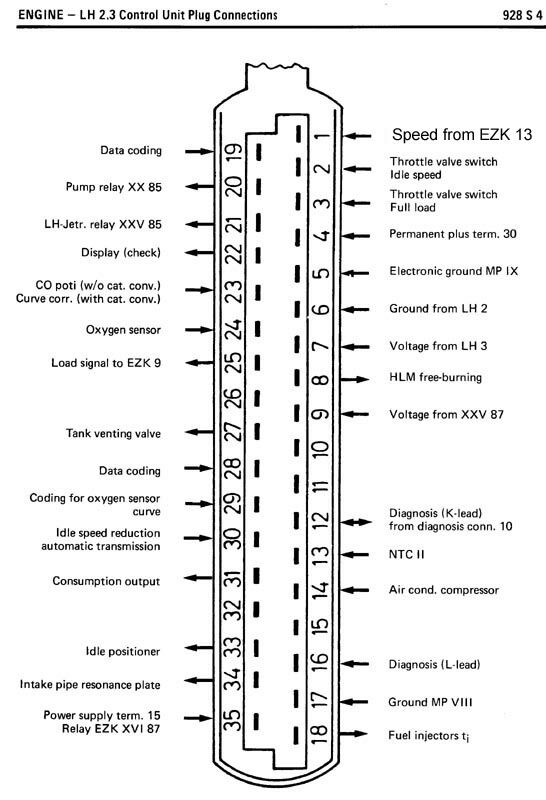
There is a small error in this diagram, LH pin #15 is actually used !! See my adjustment: LH.pdf
| Diagnostics port on a 928s4 MY 1988 | |||
| 1 | over fuse 7 to bus 15: switched 12v | ||
| 2 | gnd via MP IX + shield ground | ||
| 3 | pin 13 EZK: Speedpulse to LH pin 1 | ||
| 4 | pin 14 EZK: knock registration input from diagnose plug to EZK | ||
| 5 | over fuse 24 to bus 30: unswitched 12v | ||
| 6 | nc | ||
| 7 | nc | ||
| 8 | nc | ||
| 9 | pin 22 EZK, shielded: Hall sender pulse | ||
| 10 | pin 12 LH+EZK, shielded: K-line diagnostics | ||
| 11 | pin 22 LH: Display (check) Engine check | ||
| 12 | pin 7 EZK, shielded: L-line diagnostics | ||

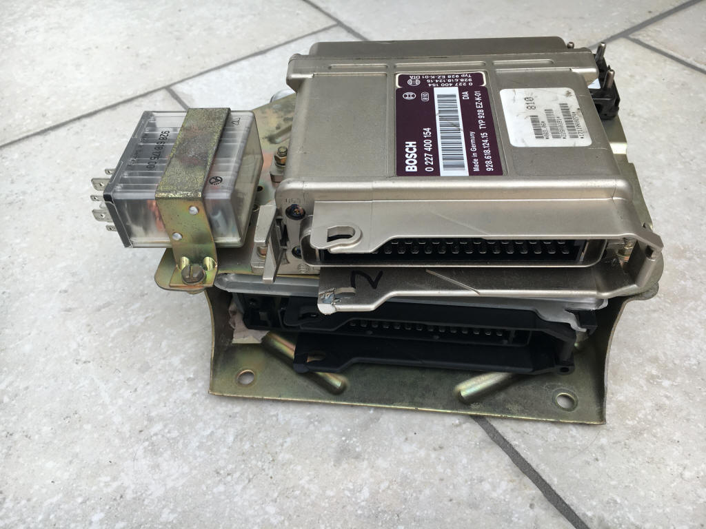
This is a picture of the early Ezk .10 ecu of which some say it does not exist:
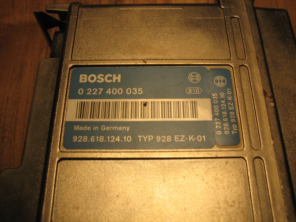
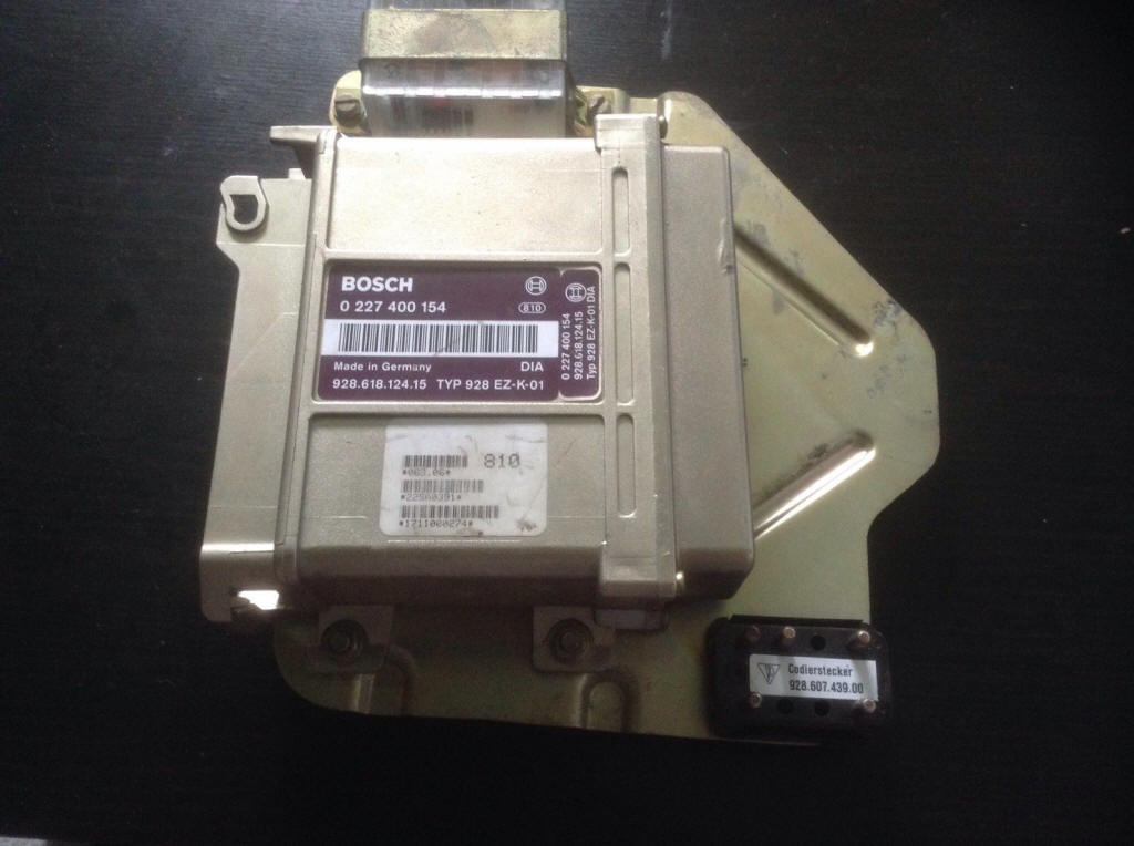

Item is a EZK ignition engine control unit from a 87 928 S4, original part # 928
618 124 11. This unit fits 87 928 S4 models.
possibly a non-dia, I'm not 100% sure, depends on the installed eprom.
At some point in time Bosch produced these ecu's in Spain. My 1988 S4 had a broken ecu and I bought one in 1999, which came from Spain factory.
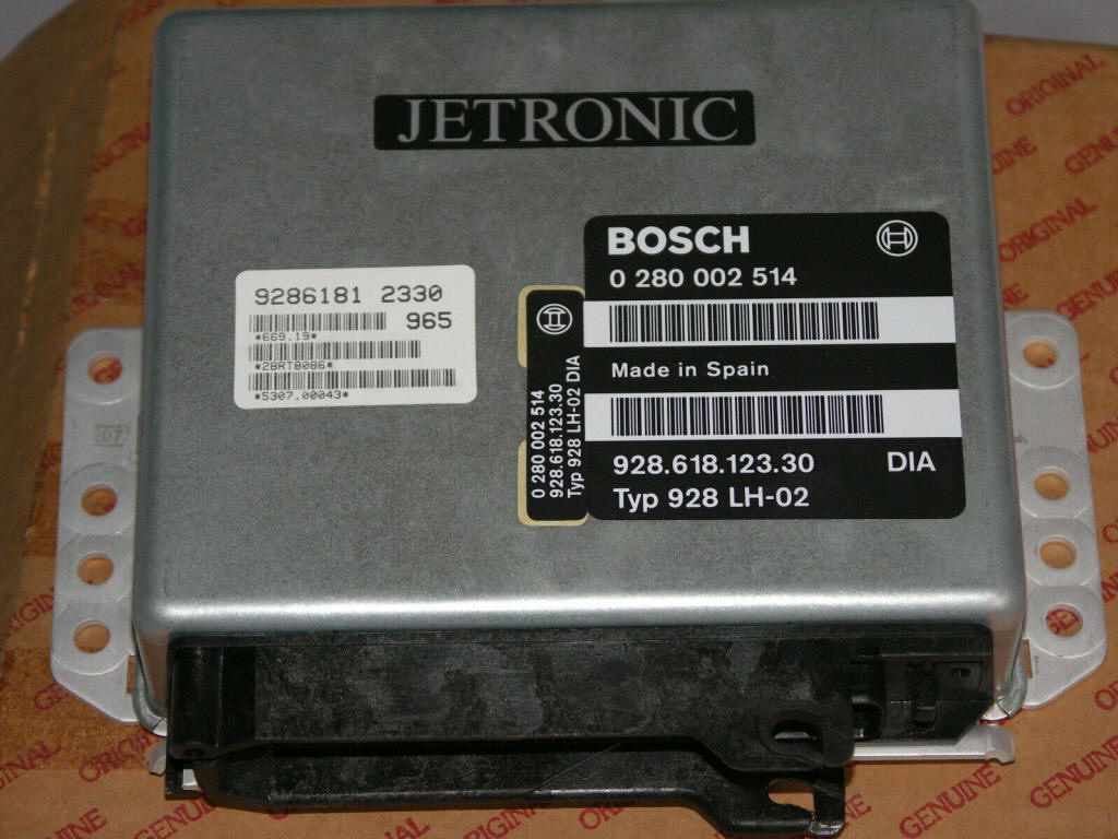
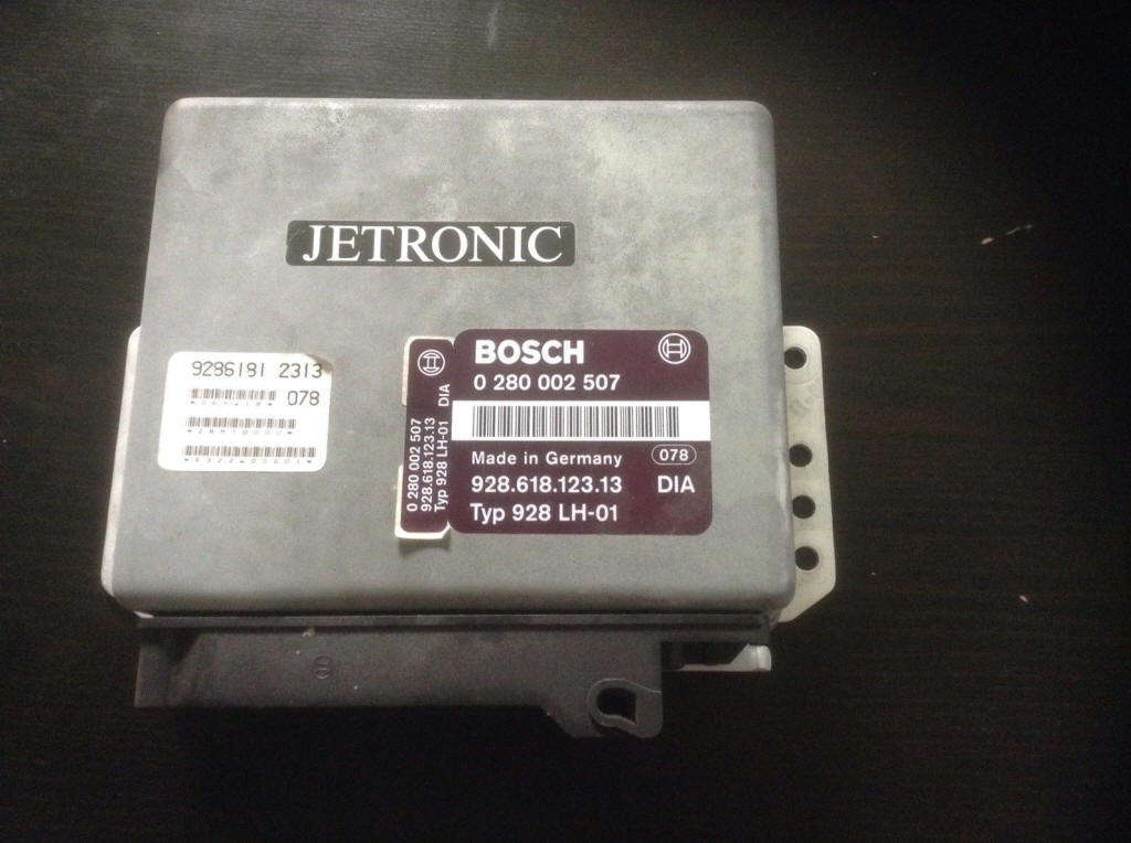
A late replacement ecu form Bosch factory in Spain. It replaces the LH2.3 of a 928S4, GT or GTS.
Some info from http://www.scotsglen.com/saab/ecu/index.htm
and http://saabnet.com/tsn/faq/lhoverview.html
LH 2.4 (Saab, I think its a late 80's or early 90's model)
some data on a LH 2.4.2
| Pin # | Lead Color | Component/Function | I/O | Voltage |
| 1 | Blue | Engine speed signal | Input | 6.5 - cranking, >8 - idle |
| 2 | Gray | Throttle Position Switch(Idle) | Input | 0 - Idle , ~11 - Above idle |
| 3 | Green/Red | Throttle Position Switch(WOT) | Input | 0 - WOT, ~11 - Before WOT |
| 4 | Red | Power supply +30 | Input | 12 |
| 5 | Black | Signal Ground | 0.0 - Separate from power ground | |
| 6 | Blue/White | Mass air flow | Ground | 0.0 - Separate from power ground |
| 7 | Orange | Mass air flow | Input | 2.0 - Idling, 5.0 - Full Load |
| 8 | Red/White | Mass air flow, burn-off | Output | 4.0 - At burn-off, 0 -otherwise |
| 9 | Gray/White | Power supply from main | Input | 12 |
| 10 | ||||
| 11 | Green/Red | A/C Time-delay Relay | ||
| 12 | Blue/White | Diagnostics lead | I/O | |
| 13 | Yellow | Temp Sensor | Input | 4(-20C) -0.5(80C) |
| 14 | Red/White | A/C, ACC load Signal | Input | 12-Auto, 0-ECON |
| 15 | Green/Yellow | Jumper for cold start | 0-no cold start, 12 cold start | |
| 16 | Green/Red | Diagnostics Lead | I/O | |
| 17 | Black/White | Chassis Ground | Ground | |
| 18 | Green/White | Injectors control signal | Output | 7.1Hz, 2.4-4.5ms |
| 19 | Yellow/White | EGR Valve | Output | 12 - inactivated, <12 active |
| 20 | Violet | Fuel Pump relay signal | 1-activ, 12-Ign on | |
| 21 | Yellow/White | Main relay operating circuit | Output | 1 - Ignition on, 12 - Ignition off |
| 22 | Violet/White | Check Engine Light | Output | 12-off, 1-on |
| 23 | Yellow/White | EGR Temp Sensor | Input | 4.5 -EGR closed, <4.5 -Open |
| 24 | Green | Oxygen Sensor | Input | 0.6 - 1.0 - Rich, 0.0 - 0.4 - Lean |
| 25 | Blue/Red | Load Signal Tq (EZK/DI) | Output | Freq incr with throttle opening |
| 26 | White | Shift-Up light | Output | 12 - Not activated,0 - Activated |
| 27 | Yellow/Red | EVAP Canister purge valve | Output | 12 - Open, 1 - Closed |
| 28 | White | PRE-IGNition, DI/APC | Input | 0-Preign, 6.5-stable, 12-knock |
| 29 | Gray/White | Codification | Input | 12 - Automatic transmission |
| 30 | Orange | Raising engine idle speed | Input | 12-R,D,1,2,3, 0 - P,N, and manual |
| 31 | Green/Red | Consumption signal to EDU | Output | Freq incr with throttle opening |
| 32 | Brown | Cold start valve | Output | Battery voltage - Not activated |
| 33 | Blue/White | IAC valve | Output | 5-11 - Idling, no load |
| 34 | Green | Speed Sensor | Input | 6 -Rotating, 0 or 12 - Stationary |
| 35 | Green/White | Power Supply +15 | Input | 12-Ign on |