From: Ben Burris [mailto:a5clmbr@msn.com]
Sent: Saturday, November 16, 2002 9:08 AM
To: 928
Subject: [928] Central Warning Brain Teaser
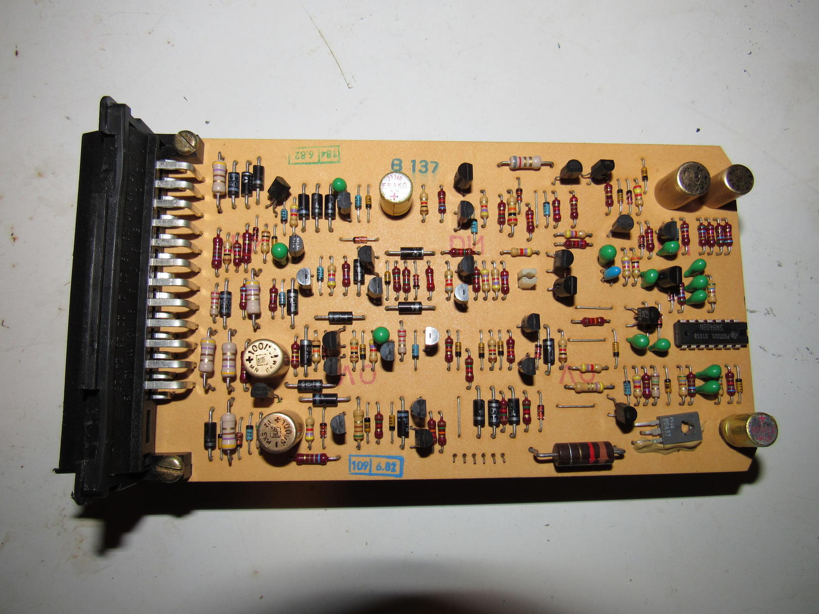
I have been troubleshooting the Central Warning Brain on my 86.5 for the past couple of days because my warning lights quit working! I am close to a fix hopefully without the cost of a new brain. I began by troubleshooting the pwr. connections for the brain using the CENTRAL WARNING UNIT CONNECTION PLAN found on pages 90-32 and 90-33 in the shop manuals. The warning brain has two connectors (25 pin), black on one and yellow on the other.
For reference to those lacking manuals: Unswitched +PWR from the battery comes into the unit on pin 21(black), switched +PWR from the ignition switch comes into pin 13 (black). There is also a GND on pin 15 (black).
I assumed (hoped) that one of the power leads feeding the Central Warning Brain was disconnected. Not so!
After finding all the power connections intact, I suspected a missing +pwr
connection that feeds the warning lights. The 928 warning system uses the
+PWR from the 15 bus as a common for each warning light and the return or
GND is switched by the Central Warning Brain to complete the circuit in a
warning condition. After realizing this I used a jumper connected to
Chassis GND and with the ignition switch in the accessory position I
grounded the pins corresponding to each light. Each light illuminated
fine as it's pin was grounded. At this point everything is eliminated
excepting the Central Warning Brain itself.
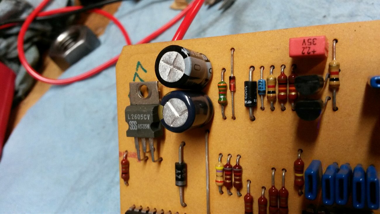
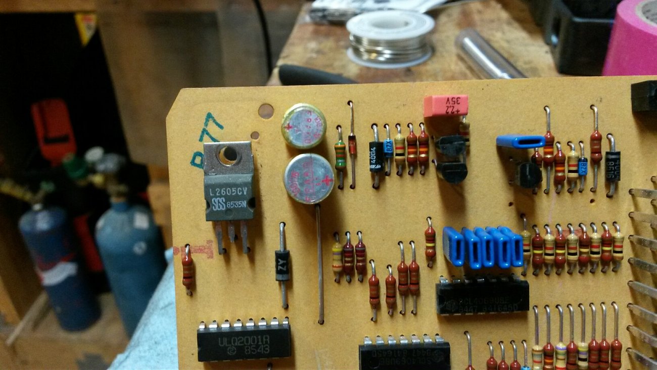
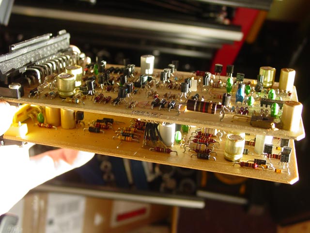
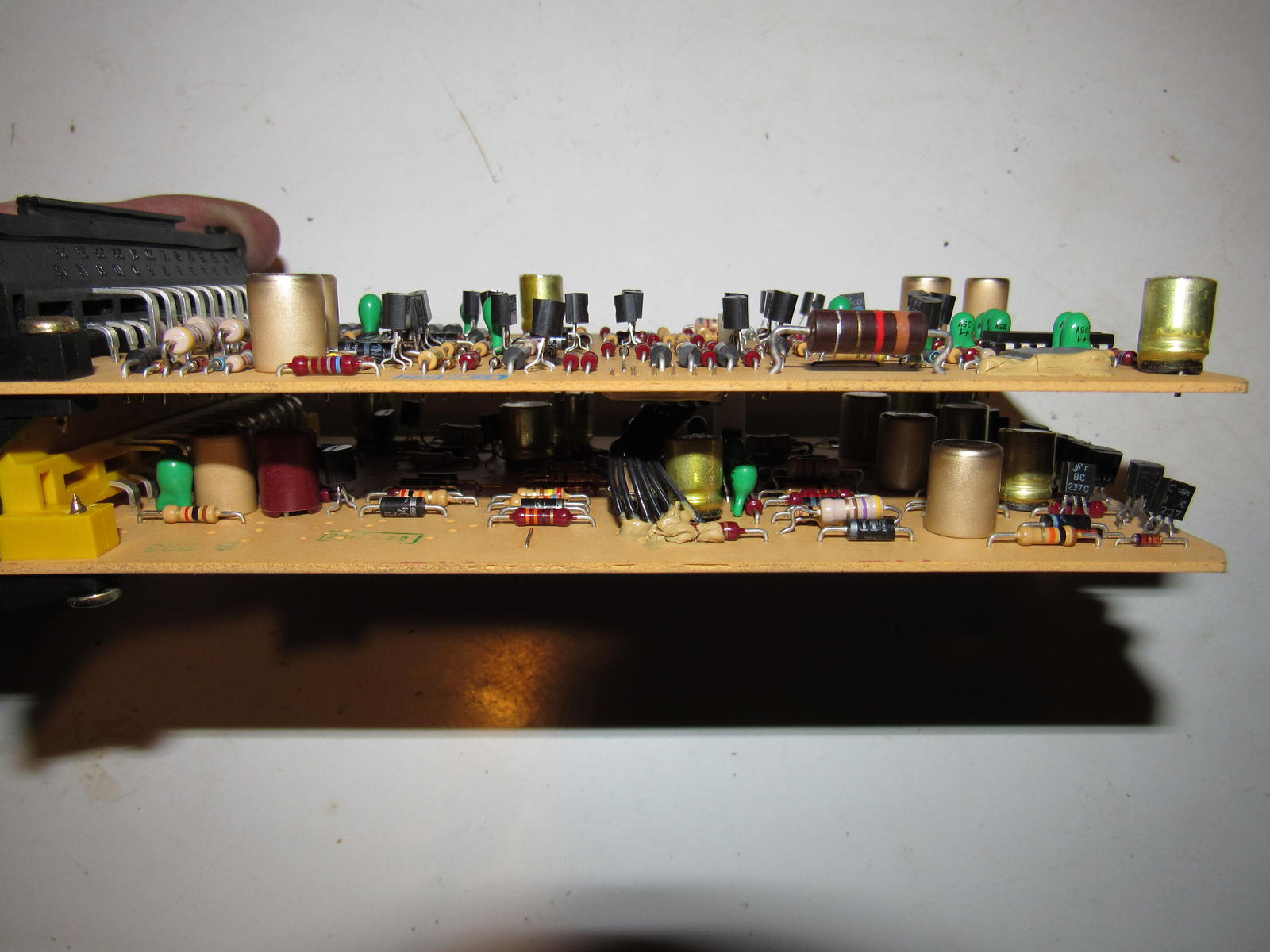
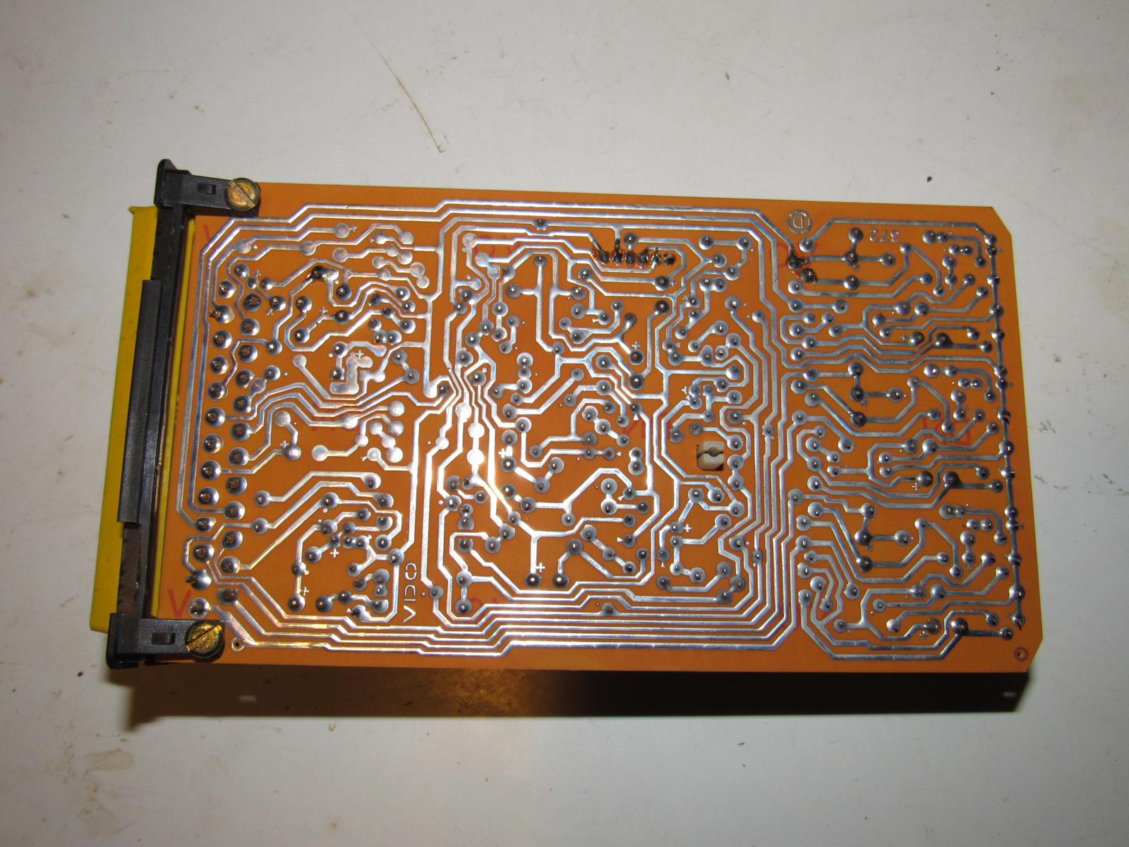
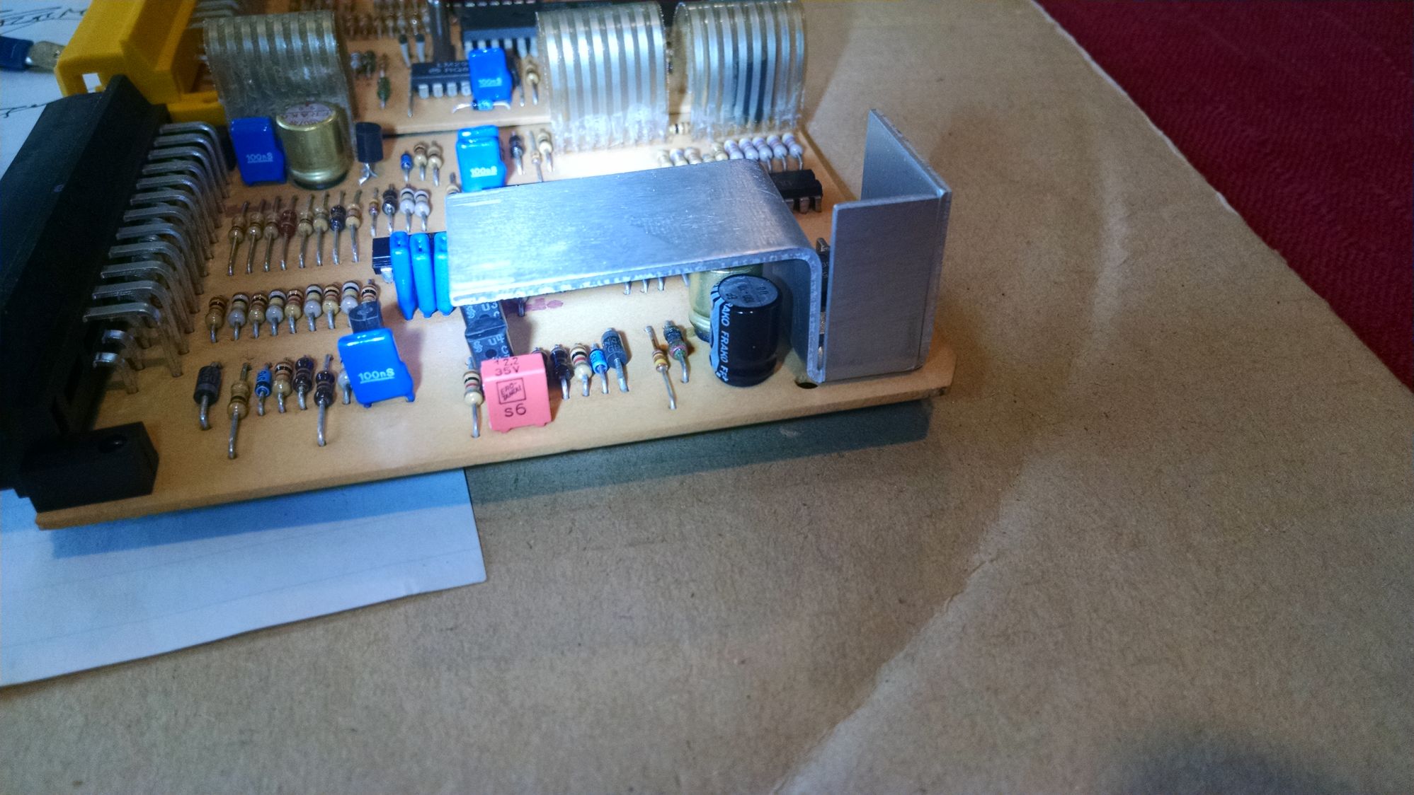
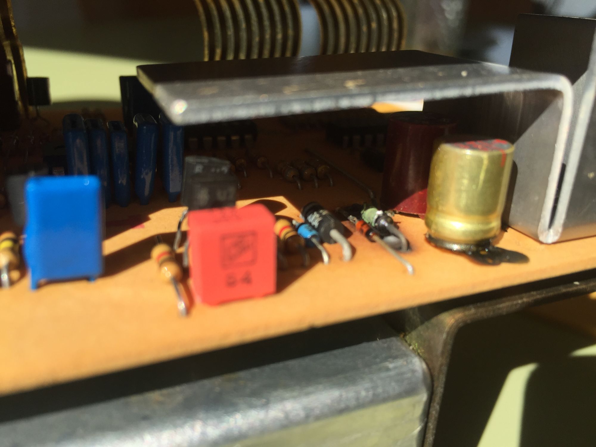
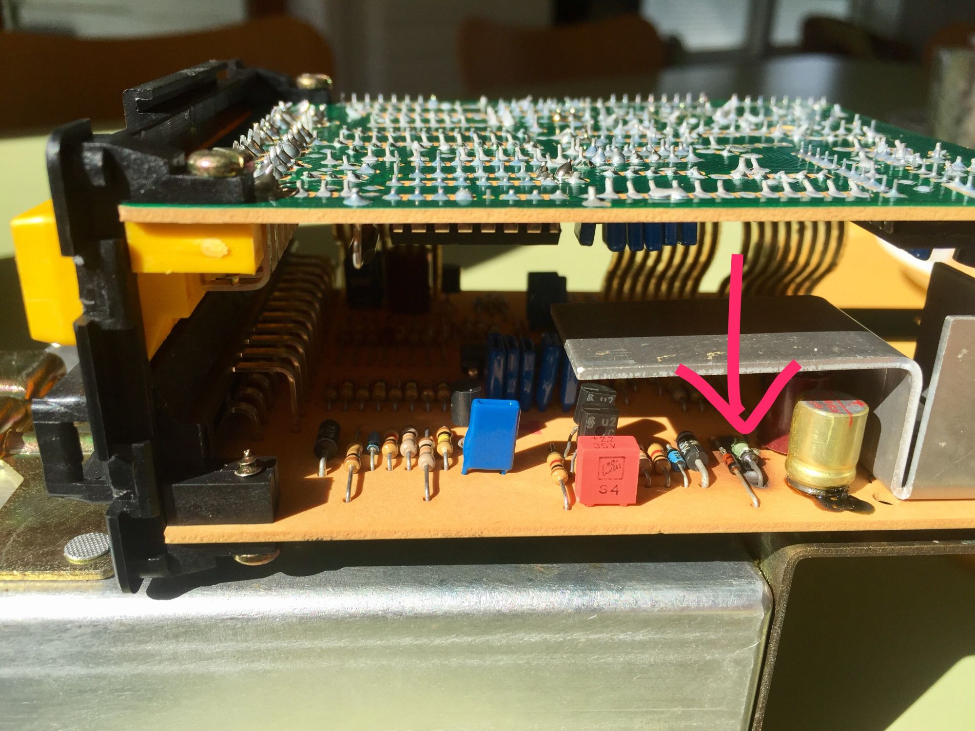
I removed the brain from the dead pedal and then from it's sheet metal enclosure to find the culprit. Inside, there are two PC boards, one on the black connector and one on the yellow. On the black connector's board there is an OP amp and a large heat sink. While looking at the unit from the side there are two capacitors side by side sitting just to the left of the heat sink. To the immediate left of the those capacitors I had a burned resistor; so badly that the color code could not be read for replacement.
Finally, my question is: does anyone have one of these warning brains
laying around and would you be willing to relay the color code of that
resistor to me? Would someone be willing to remove the brain from it's
enclosure and have a look?
hopefully some of what I have written will be of some use to others.
Ben,
86.5 indischrot
===========
The resistor has burned because the electrolytic caps used in the CWS module are aged & shorted.
Had the same thing, replaced all the parts but some of the discreet logic was damaged, and I bought a new module in the end, after wasting about 8 hours. (8*xx=more than the cost of a replacement module). My advice just get another CWS module.
I have a CWS used from a low miles S4 if you are interested.
Regards,
Paul Jager,
Jager Engineering
www.jageng.com
pjager@jageng.com
(250) 724-1402
============
I decided to use a 0-100K potentiometer across where the resistor was
placed. with the potentiometer soldered in and adjusted to 100K ohms I
turned the ignition switch on and slowly reduced the resistance on the
potentiometer until the warning lights began to function. I then locked
the shaft of the potentiometer and removed one leg for a resistance check.
After carefully repeating this procedure a few times, I consistently came
up with a figure of around 30ohms. I think the closest standard resistor
to that is 33ohms. I will have to try that permanently in place of the
potentiometer. For now all of the lights are working and I will continue
to employ this fix until that is no longer the case. If the logic
components are indeed flakey I will know soon enough at such time I will
feel a little more at ease with buying the replacement Central Warning
Brain.
How much are you asking for your used S4 Brain Paul? The figures I have come across from "The Big Three" for a Central Warning Brain are a lot more than what 8 hours of MY time is worth!
The small cap has this printed on it: 100/10 FRAKO P 5
Then larger cap has this printing : 100/16 FRAKO S 2
I'm guessing the smaller cap is 100mF 10V
and the large is 100mF 16 V
One of the electrolytic capacitors failed. I replaced all four of them with
higher voltage and temperature ones. Cost about $1. The burned resistor is 2.4
ohm 5% - about 4 cents. I also replaced the "ribbon" cables connecting the 2
halves.
Thanks,
Brian