TC Components and Power Flow
Torque Converter Components
Impeller - The impeller is driven through the converter cover by
the engine flex plate. It is the "input" member of the converter
assembly and makes up the second half of the of the converter outer casing.
Stator - This is the stationary or "reaction" member
for torque multiplication. It controls oil flow from the impeller in the
"reduction" phase of converter operation.
Turbine - The turbine is driven by oil splashed from the
impeller. The turbine is the output member of the converter which drives the
turbine shaft of the transmission.
Damper Assembly - The Damper is welded to the converter cover. It
cushions engine shock to the direct drive shaft of the transmission.
Stator Support - The stator within the converter is splined onto
the stator support: the stationary shaft extending from the front of the
transmission pump.
Impeller Hub - The hub is a steel collar welded to the impeller
which mechanically drives the gears of the transmission pump.
The converter is supported on the stator support [5],
which is part of the transmission oil pump assembly. The impeller hub [6]
is supported by the transmission pump body bushing.
Power to the Gear Train
Depending on which gear the transmission is in, input from the engine to the
transmission is through the turbine input shaft or the direct drive shaft or a
combination of both.
- In reverse, first and second gears, the turbine input shaft transmits
torque from the turbine to the reverse clutch or forward clutch. This a
hydraulic drive, since the impeller must drive the turbine with hydraulic
oil.
- In fourth gear (overdrive), the direct drive input shaft transmits torque
to the rear (direct) clutch. This is a solid (mechanical) drive, since the
turbine is by-passed. The damper assembly drives the shaft at engine speed.
- In third gear torque is split between the two shafts. The drive torque is
about 40% hydraulic and 60% mechanical.
How the Converter Works
7
Automatic Hydraulic Clutch
In Reverse, low and second gears, the converter operates in hydraulic or soft
drive conditions. In hydraulic drive, the converter functions as an automatic
clutch (when the car is stopped) and as a torque multiplier (when engine load
requires more torque).
- The engine drives the impeller mechanically.
- The turbine is driven hydraulically by the impeller.
- The turbine drives the tube input shaft for input to the gear train.
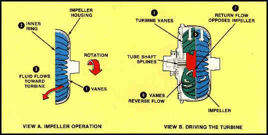
Impeller Pumps Fluid
The purpose of the impeller is to put the fluid in motion. Inside the impeller
housing many curved vanes, along with an inner ring, form passages for the fluid
to flow through. The rotating impeller acts as a centrifugal pump. Fluid is
supplied by the hydraulic control system and flows into the passages between the
vanes [1]. When the impeller turns, the vanes
accelerate the fluid and centrifugal force pushes the fluid outward so that it
is discharged from openings around the inner ring [2].
The curvature of the impeller vanes directs the fluid toward the turbine, and in
the same direction as impeller rotation [3].
Rotary Force on the Turbine
As shown in View B (above), the turbine vanes [4]
in the turbine are curved opposite to the impeller. The impact of the moving
fluid on the turbine vanes [5] exerts a force that
tends to turn the turbine in the same direction as the impeller rotation. When
this force creates a great enough torque on the transmission turbine output
shaft to overcome the resistance of motion, the turbine begins to rotate.
Now the impeller and turbine are acting as a simple fluid coupling, but we
have no torque multiplication yet. To get torque multiplication, we must return
the fluid from the turbine to the impeller and accelerate the fluid again to
increase its force on the turbine.
Vanes Reverse the Flow
To get maximum force on the turbine vanes when the moving fluid strikes them,
the vanes are curved to reverse the direction of flow [6].
Less force would be obtained if the turbine deflected the fluid instead of
reversing it. At any stall condition, with the transmission in gear and the
engine running but the turbine standing still, the fluid is reversed by the
turbine vanes and pointed back to the impeller. Without the stator, any momentum
left in the fluid after it leaves the turbine [7]
would resist the rotation of the impeller.
At this point, we have a simple fluid coupling that will cause the turbine to
drive the input shaft with no torque multiplication. To gain multiplication, we
must add the reaction member or stator.
Torque Multiplication and Coupling
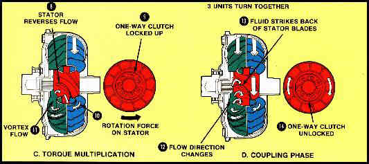
Torque Multiplication
When torque multiplication is required, the stator [8]
above reverses the direction of impeller rotation. A one-way clutch [9]
prevents the force of the fluid from turning the stator opposite the impeller
and turbine by holding itself motionless on the stator shaft.
As the fluid flows from the stator to the impeller, the impeller has another
opportunity to accelerate the same fluid. The fluid [10]
leaves the impeller with close twice the energy it had the first time and exerts
greater force on the turbine.
We call the flow of fluid [11] through the
impeller, to the turbine, through the stator, and back through the impeller the
vortex flow. At high impeller speed and low turbine speed. the vortex flow
velocity is the sum of the impeller produced velocity, plus the velocity of the
fluid returning from the turbine and stator. It is vortex flow that gives us
torque multiplication.
By torque multiplication, we mean that there is more torque on the turbine
shaft than the engine is putting out because the vortex fluid is accelerated
more than once. Torque multiplication is obtained at the sacrifice of turbine
rotation. Actually, it's no different from the mechanical advantage which your
get from gearing down. You gain torque by sacrificing motion.
Torque multiplication takes place anytime the turbine is turning at less than
9/10 impeller speed. At full stall, the stock AOD converter produces about
1.85-to-1 torque multiplication. As the turbine speed increases in relation to
the impeller, torque multiplication decreases.
Coupling Phase
When the coupling phase (view D above) is reached - when the turbine speed is
about 9/10 impeller speed - there is no longer any torque multiplication. The
converter is then only transmission engine torque to the gear train.
As the turbine begins to rotate and steadily picks up speed, the vortex flow
steadily looses speed because of the increasing centrifugal force acting against
the flow through the turbine. The rotating impeller produced a centrifugal force
in the fluid which caused it to flow from the center outward. The same
centrifugal force is acting in the rotating turbine, trying to prevent the fluid
from flowing inward. As the vortex flow slows down, torque multiplication is
reduced.
As the turbine catches up with the impeller, the angle at which the fluid
leaves the turbine is constantly changing [12]. In
the coupling phase, the fluid leaving the turbine strikes back at the stator
vanes [13]. The one-way clutch unlocks [14]
and the impeller, turbine and stator turn together. Allowing the stator to
rotate freely during coupling lets the fluid moved by the impeller to flow
directly into the turbine.
Converter Automatically Adjusts Torque
Since vortex flow speed is governed by the difference between impeller and
turbine speed, the torque converter output to drive shaft torque requirements.
When drive shaft torque requirements become greater than the engine output
torque, the turbine slows down and causes an increase in vortex flow velocity
and therefore an increase in torque multiplication.