Having replaced one recently on my 83 over at Greg Nichols where he
related his experience changing his out on an 87, you should find it in
the front right corner beneath the console (Radio, climate control, shift,
etc.).
Remove the passenger side shelf attached by 4 10mm (or is it 8mm?) bolts.
Remove the passenger side carpeted trim panel below the console held in
place by 1 phillips screw toward bottom middle, and 1 interior clip below
the area of the window switches (give it a firm pull).
==================
Having replaced one recently on my 83 over at Greg Nichols where he
related his experience changing his out on an 87, you should find it in
the front right corner beneath the console (Radio, climate control, shift,
etc.).
Remove the passenger side shelf attached by 4 10mm (or is it 8mm?) bolts.
Remove the passenger side carpeted trim panel below the console held in
place by 1 phillips screw toward bottom middle, and 1 interior clip below
the area of the window switches (give it a firm pull). Pull the panel
sideways (at an angle bottom first so the top lip clears from under the
console) and it slides off the mounting bracket for the passenger side
shelf and comes free.
You will find the CC control unit directly under the heating vent by the
fire wall. Mine was held in place by one 7mm bolt (yup, strange size and
it appeared to be factory installed). Remove the bolt and you can then
wiggle the unit out past the wiring running around the area, and unplug
it.
Replace in reverse order.
Regards,
John Eifert
===========
Cruise control unit repair
Eureka!! Just located this
summary of cruise controls uses on MB's They use
the same VDO unit as used in 928's. The author is well known to some of us
as the guy who will fix your control unit for $150 US. I was especially
interested in item 4 which has been my experience.
Peter Mathew.
'81 928SEuro Auto,
Hellblaumetallic
TROUBLESHOOTING YOUR CRUISE CONTROL
by
George Murphy
The factory-installed cruise control provided on Mercedes-Benz
automobiles works very well for the first 4 to 5 years of operation. It is
rock steady
up hill and down and really a leg saver on long trips. But with time, the
components in the system age and begin to cause trouble. The first
indication
can be intermittent loss of control or even total failure. In this article
I
will cover common problems I have encountered in the 8 years I have owned my
1978 300D and the experience of other owners who have contacted me with cruise
control (CC) problems.
NOTE: The repair technique outlined below for the printed circuit board has
been successful in about 2/3 of the cases I have encountered - but it is
worth a try before replacing this outrageously
expensive device.
There are three major components in the CC system: the control unit, the
transducer, and the throttle servo unit.
Control Unit: this device compares the actual speed of the car and the
selected speed. In the event of a deviation from the selected speed the
control unit sends pertinent control signals to the vacuum- or
electrically- actuated throttle servo unit until the actual and selected
speeds are again in agreement.
Transducer: a speed sensor mounted on the speedometer cable (early
version) or on the speedometer (later version). The transducer sends the
actual speed signal to the Control unit.
Throttle servo unit: (early version) a vacuum-actuated servo which
positions the engine throttle to attain the selected speed. Later versions
utilize an electric servomotor.
In order to trouble-shoot the system, you should have a digital volt-ohm
meter, some test leads with alligator clips, plus straight and Phillips-head
screwdrivers, metric wrenches, and a trouble light. But first of all, check
the obvious - is the fuse blown?
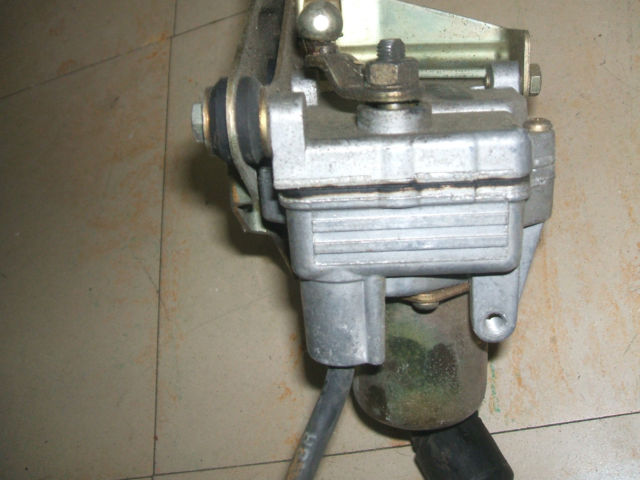
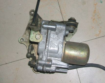
1. Locate the throttle servo unit in the engine compartment. The vacuum unit
is similar to that shown in Figure 1. Check the vacuum and vent lines -
replace the small rubber hose couplings if they are cracked. Age and heat
can cause deterioration of these rubber parts - as well as other couplings under
the hood (and throughout the car).
The electric unit looks like a small metal box with a linkage connected to
the throttle. Check that the linkage is secure.
2. (Vacuum units only) Pull the 2-pole connector from the throttle servo
unit. Connect an ohmmeter to the servo unit pins. The resistance should be
between
10 and 22 ohms; if not, replace the throttle servo unit.
3. (Vacuum units only) Follow the actuating cable from the servo to the engine
throttle linkage. Check that the end of the actuating cable is just
touching
the throttle lever with the least possible free play, but not exerting any
force on it (otherwise the engine idle could be increased). If the end of
the actuating cable is not touching the linkage, turn the adjusting nut (Figure
2) in such a manner that the end of the actuating cable just touches the
throttle linkage. CAUTION: on diesels, turn the idle speed adjuster knob
completely
to the right and hold the emergency stop lever (on the throttle linkage) all
the way to its stop before adjusting the nut.
This adjustment assures that the vacuum-operated throttle servo unit is
operating in the middle of its range, which gives the best control and
response.
4. To check the speed transducer, remove the left hand cover under the
instrument panel. On early models the transducer is located in line with the
speedometer cable. On later models, it is a small black box about 1" square
mounted on the back of the speedometer head. (You may have to push the
instrument cluster out of the dashboard to reach the back side of the
speedometer). Unplug the 2-pole connector from the transducer. Connect an
ohmmeter to the transducer. Early models should read 50 to 106 ohms; later
versions should read 650 to 1370 ohms. If these values are not attained,
replace the transducer.
If the above steps do not solve your CC problem, then the control unit could
be at fault. In order to do any repair on the control unit, you will need a
soldering iron of not more than 25 watts, plus a small amount of fine resin
core solder wire. (These can be obtained at Radio Shack for a few dollars)
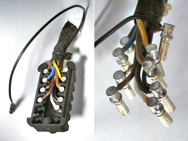
1. Remove the left hand cover under the instrument panel. The control unit
is contained in an aluminum box about 1" by 4" by 7" and is
secured by a single
bolt to the brake pedal bearing bracket. Remove the bolt, unplug the
electrical coupling from the unit, and remove the unit from the car.
2. Carefully bend back the crimps on the aluminum housing so the printed
circuit board can be withdrawn from the box.
3. Inspect both sides of the printed circuit board for burned or melted
components. If there are any, the unit will have to be replaced. If the
board
does not show any obvious signs of overheating, it may be repairable.
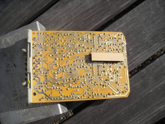
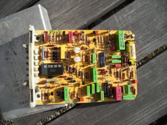
4. Look at the two sides of the printed circuit board - mounted on the
component side are various transistors, diodes, and integrated circuits; and
on the "foil" side is a confusing pattern of thin copper foil
"wires" soldered
to the wire leads of the various parts on the opposite side. The control unit
generally fails whenever one or more of the soldered connections on the foil
side become loose due to vibration or heat. If you are very careful, it is
possible to resolder these connections and get the unit working again. For
this task, you will need a steady hand and the 25 watt soldering iron (and
possibly a magnifying glass to inspect your work).
5. Solidly position the printed circuit board foil side up in a well lighted
work area. Starting at one end of the board, carefully apply heat with the
tip of the soldering iron to each solder joint on the board. CAUTION: Apply
only enough heat to cause the solder around the connecting wire or lug to
momentarily melt, then remove the soldering iron and allow the soldered joint
to "freeze". Make sure no solder flowed to an adjacent
connection or you
will have a short circuit. You may add a small amount of solder if the
joint
appears to be lacking enough for a good connection. The solid state devices
cannot tolerate excessive heat, so use care with the soldering iron.
6. After you have resoldered each connection on the board, closely inspect
for solder "bridges" between connections which can cause a short
circuit. The
connections may appear slightly discolored from your resoldering efforts,
but no harm should occur if you were careful with the heat.
7. Replace the printed circuit board in its housing and carefully recrimp the
sides of the box. Reinstall the unit in the car and make sure all connections
are secure. Be sure to check the fuse for the unit in the fuse enclosure.
8. IMPORTANT If you are not sure, check that the brake light bulb in each
tail light unit of your car is an original equipment OSRAM or BOSCH bulb. DO NOT
USE U.S. TYPE 1157 BULBS - THEY CAN DAMAGE THE CONTROL UNIT BEYOND REPAIR!
The correct bulbs are available from your M-B parts supplier.
9. Take the car out for a road test and actuate the CC in accordance with the
owners manual to make sure it works properly.
Good luck!
G. Murphy
======================================================
Dan,
I have had every piece of the cruise control system out on my 87.
When you
say the cruise control unit, I assume you mean the electronic brain.
Below
are the instructions for removing it:
1) Remove the carpeted panel on the passenger side of the center console.
You may need to remove the knick-knack tray (or at least loosen it) to get
it out.
2) The cruise control brain is located in the center console right next to
the fire wall (about 6" or so from the back of the stereo head unit.)
It's
a silver aluminum box about 5" X 4" X 1". It will be
held in place by a
single bolt you can get to from the passenger side.
3) To make things easier, you may want to disconnect a few of the wire
bundles running between you and the cruise unit. There are several
with
connectors you can easily disconnect. This will give you more
working
room.
4) Once you get the single bolt out, you can pull the unit out, but it will
be a little tight.
5) Once you have it out, disconnect the 12 (I think it's 12) pin connector
on the back.
6) Send the unit off for repair, and cross your fingers that was the
problem!!!
If you have any more questions, please feel free to ask.
Good luck!
Randy
87 S4 Auto Black/Black
===========