
First check if the fans run as described in the page I sent the link of. That will point you to a power stage if the fans run when bridging connections.
Theo
http://928gts.jenniskens.eu
======
Bob, and others on the list.
Thanks for the help provided. Got it fixed now.
Let me share the procedure with you.
--------------Problem--------
One fan runs at max at all times. The other is running
controlled the way it should. I can only shut it down by
pulling the connector out on the fan.
I've tried disconnecting:
1. the water temp sensors (both on the front of the engine)
2. the coolant temp sensor (right side down on the radiator)
3. Freon pressure and Freon temp (at the unit just in front of radiator)
4. manifold air temp sensor (on top of the manifold)
5. is there still one more sensor for fluid temp of the AT ? (don't know)
Checking means: pulled out the sensor connectors and left open all at
once.
--------------Solution---------
This is the procedure :
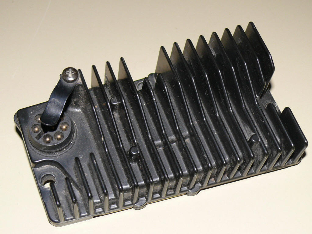
The control unit is located on the front-right side (seen from driver position) of the engine
compartment.
It is the one with the finned heat sink on top and the round connector.
1. unplug the connector and the 3x10mm screws
2. pry off the bottom plate with a screwdriver. (careful, you'll need it
later)
3. take out the insulation plate (brown, loosely placed inside)
4. take off the rubber seal ring
5. take out the 4 Phillips screws that hold the PCB
6. carefully push out the round connector (it has a rubber ring that seals it)
7. there are two assembly's that carry the power drivers for the fans both sets are independent for one fan. They are equipped with
2x N-channel MOS FET's (like transistor type). Specs: 50V, 26A
max load
8. if in doubt of correct functioning, just replace the components (2$ each)
9. drill out the part that holds the FET in place on the heat-sink
10. solder out the old FET (s). Carefully; use a TIN suction pump is available.
11. drill a hole through the heat sink and make screw thread in it to hold the
new FET
12. attach the new FET (s) using a standard screw and use silicone paste to make a good temp-conducting mount on the
heat-sink
13. solder in the new FET (s)
14. re-attach everything in reverse order. Try to keep the bottom plate fixed,
and best: make screws in to re-attach properly so that it seals again.
Guess what.... it run's ok again.
If you experience problems with the control unit itself... don't worry.
Just replace all non resistor and capacitors. All are standard components. Some
diodes are special, so check !
The PCB does look half as complicated as the fuel computer.
Again, thanks to Bob for his help in the matter!!!!
Theo Jenniskens
'88 928s4 Cherry Red
The Netherlands
=======
The fan power needs are quite large:
Fan reads about 17 Amps steady load, inrush/surge was less
than 20 Amps.
Unplugged both fuses so the controller would see a fault when testing just one,
and force high speed. AC running to get the fans on. Middle speed is about 10
Amps running.