- DR sent me the Official Timing Belt Tensioner and I
have been playing :-)
The object of my games is to make a cheap alternative. Here are my
results, please anyone feel free to comment ( constructively
that is)
Theory.............
Tension is easy to measure in a belt when access is available to the
points of external force being applied. If we could somehow
measure the side load in the camshaft bearings for example and
then divide it in two we would have a figure of belt tension. This we
cannot do, so other methods are needed. The approach is based on the
elastic properties of the belt material. As the tension is increased
the belt stretches. So if at a given tension the overall length og the
belt is X mm. then if we increase the tension of the belt by adding a
given extra belt length path then we can calculate the original
tension ( assuming linearity in belt length to tension over this
range)
So if we increase the distance by which the belt must travel , by such
means as the 'wiggle' in the Official Tool, by a small percentage, dt
(%), then the tension will increase by dt as well. Knowing dt will
enable us to know the value of T, the actual belt tension. Of course
in practice the actual values of tension and wiggle are replaced by
easy read number scale ( 0 to 10 in this case)
All we need is a tool which will 'deform' the straight section of belt
by a fixed amount and then measure the force needed.
Assumptions
Introducing a wiggle in the belt ( or a twist as per the finger thumb
method)
has its results also dependant on certain belt material properties,
properties that can vary with age, temperature, and possibly oil
contamination and humidity. It is probably best to assume the Official
Tool and all derivatives thereof are most accurate on a new belt
Experimentation
Well I did several things :-)
First I ran a a finger thumb method test, setting tension by the
Finger thumb 90 degree test method several times and recording the
actual tensions with the Official Tool Results, not too accurate,
ranging from 3.0 to 6.3 ( Book figure of 4.5 is correct). Whilst this
method puts the tension ion the correct order of magnitude it is NOT
at all accurate ( no surprises here)
Next I made a little device with telescopic tubes and springs and
measuring rule, the idea was that by applying a known pressure I could
adjust the tension such as to allow the belt to deflect a known amount
After an hour of welding, grinding and making this thing, it was only
a
little more accurate thew the finger thumb method. Results of same
test range from 3.6 to 5.8, NO ***** good
Not to give up and realizing that the problem was not with the method
but with the accuracy with which reading can be made I decided to go
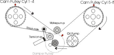
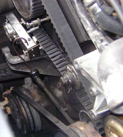
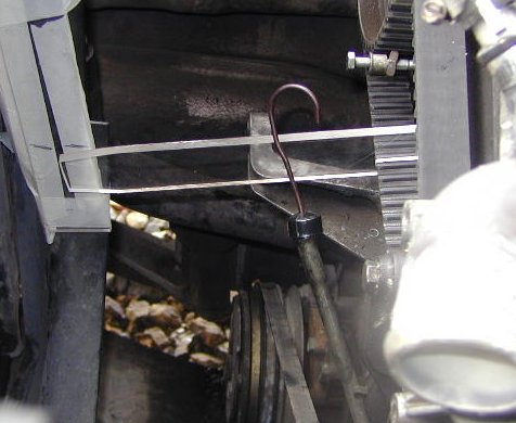
for a variation of the Thumb twist method I cut a section of clear
acrylic about 1.5 inches wide and I guess 8 inches long ( just fits
between belt at air pump and the radiator. I cut a slot so it would
fit snuggly between the slots on the belt. then I set the tension with
the Official Tool to 4.5. Sitting this acrylic on the belt in place of
the Tool, it twisted the belt by its own weight about 1.2 inches down
from the horizontal. I then ground the far end of the acrylic to 1.2
inches. Now, by simply setting the level and marking with tape on the
radiator, all I have to do is to slide my acrylic tool on the belt and
adjust the tension until the top edge of the acrylic is in line with
the level mark. Its own weight drops it that much. This is incredibly
accurate, simple and cheap. I found repeatability excellent. Setting
up wit this tool gave results of 4.4, to 4.6 every time, in fact it
may be the Official Tool that is not very repeatable.
So, if anyone wants more detail, measurements or whatever, just ask.
This is a cheap easy accurate method to set tension, with greater
readability than the dial gauge Official Tool Anyone see any problems
with this method? I found the belt twist to be approx 10 degrees, so
belt properties are kept to a minimum.
Phil
|