Oxygen (O2) Sensor, Open Loop and Closed Loop Operation


The oxygen sensor is mounted in the exhaust pipe just after the turbo exit. The O2 sensor has a internal heating element to ensure quick warm up and correct operation at idle. There are three wires going into the O2 sensor on the Audi Turbo. One ground, one +12V signal, and one for the actual O2 sensor output voltage.

If you have trouble with the O2 sensor working correctly at idle, the heating element inside the sensor may be defective. The fuel pump relay supplies +12V to this sensor and to other engine solenoids through circuit 87a, you should check for +12V and ground across the two terminal connector to the O2 sensor with the engine running. You can also check the heater inside the O2 sensor by disconnecting the two terminal connector for the O2 sensor heating circuit, and then measure the resistance across the O2 sensor heating element, it should read around 5 ohms, but this resistance will vary a little as the sensor warms up. The resistance will read open circuit (infinity ohms) if the element is burned out.

The sensor heating element draws 1.7 amps when first energized, the current will drop to around 1.0 amps after the heating element gets warm.

The O2 sensor incorporates a vent to outside ambient air for a reference to compare to the oxygen level in the exhaust gas. This vent is normally in the area where the wires exit the sensor, so be careful not to get water or other debris in the top of the O2 sensor when cleaning the engine.

Here is a picture of the O2 sensor with it removed from the exhaust down pipe.


When the engine is first started when it is cold, the engine will briefly run for 1 or 2 minutes in open loop operation based on the "basic" idle mixture setting in the CIS Fuel Distributor/Air Flow Meter assembly and by the duty cycle programmed into the ECU.

Normally the basic idle mixture is set to be 0.6% to 1.2% Carbon Monoxide (CO) when the exhaust gas is measured up stream of the catalytic convertor. Once the Oxygen (O2) Sensor warms up (Heated O2 sensor), the system will switch over to closed loop operation.

This sensor is used to monitor oxygen levels in the exhaust and acts as a voltage supply that transitions high to low when the oxygen level is high (slightly lean above 14:7 to 1 air fuel ratio) and transitions low to high when the Oxygen level is low (slightly rich air fuel mixture below 14:7 to 1 air fuel ratio). The ECU uses this oxygen sensor signal to tweak the air fuel mixture back and forth close to the ideal 14.7 to 1 Air Fuel Ratio.

With the fuel system in closed loop operation after the O2 sensor warms up, the O2 sensor voltage cycles up and down between ~0.1V and ~0.9V. At idle, the O2 voltage should cycle back and forth 1 to 2 times per second and when cruising, it should cycle back and forth ~4 to 5 times per second. This cycling occurs because the engine computer senses the O2 voltage and then changes the duty cycle going to the CIS Frequency valve (Mixture solenoid). This Frequency valve alters the lower chamber pressure in the fuel distributor which alters the fuel flow out to the injector.

This switching action allows the ECU to do minor adjustments to the air fuel ratio to allow the catalytic convertor to perform its job to optimize the "oxidation" of Carbon Monoxide (CO) and Hydrocarbons (HC) and the reduction of Nitrogen Oxides (NOx). The oxidation occurs when the mixture is slightly lean and more oxygen is available, and the reduction occurs when the mixture is slightly rich and less oxygen is available.

These chemical reactions that occur in the catalytic convertor ensure the lowest possible emissions out the tailpipe. Catalytic convertors typically operate at 60-90% efficiency depending on age. This means that the amount of exhaust emissions that enter the catalytic convertor are reduced approximately by this percentage. For example, in the Audi I5 turbo engine, at idle, you typically have exhaust gas entering the catalytic convertor with a Carbon Monoxide (CO) level of 1.2%, this will be reduced to ~ 0.36% to as measured at the tailpipe with a 70% efficient convertor.

Here is a chart showing the relationship between the various exhaust gases and air/fuel ratios.


You can watch the Frequency valve duty cycle change back and forth on an oscilloscope screen and if you connect up the O2 voltage signal on channel 2 and the frequency valve signal on channel 1 of the o-scope. You will see how the high (rich) O2 voltage will cause the frequency valve duty cycle to be reduced in order to lean out the mixture.

NOTE: If the Oxygen sensor or wiring fails, the ECU will use a 50% duty cycle to operate the frequency valve.

O2 SENSOR - TESTING

If the O2 sensor wire is disconnected with the engine running, the ECU normally has a 0.450 V (+/- 0.050V) reference voltage on the ECU wire connecting to the O2 sensor. The ECU will switch over to a basic idle mixture setting with the O2 sensor disconnected. The ECU O2 signal wire is the large green wire with male and female spade connector under the small rubber boot. The 1986-88 5000 Turbo and 5000 Turbo Quattros have this O2 sensor green wire and rubber boot over the connector laying along the right fender lip and the fuel distributor/air flow meter assembly. The later 89-90 200T/Q with the dual knock sensor MC engine have this rubber boot connection on the back engine firewall area on the bracket with the other color coded connectors.

DMM TESTING

You can also use a Digital Multimeter (DMM) to do a basic test of the O2 sensor voltage with the sensor connected to the ECU, but the meter normally will not respond quickly enough to see the voltage go up and down. It is important to know what the input impedance is of the meter you are connecting across the O2 sensor or for that matter across any of the ECU inputs/outputs. Most modern DMM's have a 10 Mega-ohm input impedance. Many of the older analog meters have a input impedance down below 100K ohms. These older meters "may" work once your O2 sensor is warmed up as the impedance of the O2 sensor usually drops to 5-20k ohms.

If your DMM has a "analog" type bar graph feature, you can measure the O2 voltage and see changes, as this bar graph display responds quicker and this can be used to monitor the O2 sensor voltage as it swings high and low when the ECU/fuel system is in closed loop operation.

If the DMM has a "zero" feature to zero out the bar graph reading with a voltage applied, you can connect the DMM to the O2 sensor wire and turn on the ignition before starting the warm engine. The DMM should read ~0.45V with the meter connected to the O2 sensor wire with the ignition on, but with the engine not running. Now zero out the 0.45V reading, and start the engine. The DMM bar graph should oscillate up and down around this 0.45V reference voltage 1 to 2 times per second, indicating that the system is in closed loop operation.

OSCILLOSCOPE TESTING

One test you can do with the O2 sensor wire connected to the ECU, is to use an oscilloscope to measure the O2 sensor voltage and then force the mixture rich with the slow addition of propane into the intake system. The O2 sensor voltage should rise up to at least 0.85 volts. Then force the mixture lean by creating a huge vacuum leak and measure the O2 voltage transition time when the voltage drops from high to low.

To quickly force the mixture lean, you can pull off a large hose from the intake manifold, or remove the oil cap from the valve cover (10V Turbo only). This will make the engine stall but you can capture the O2 voltage response on the digital oscilloscope.

Typical transition times are around 25-50ms, the rule of thumb is that the O2 sensor transition time from 0.6V to 0.3V or from 0.3 to 0.6V should be under 100ms. The O2 sensor will have a different transition time going from rich to lean than from lean to rich, if I remember correctly the rich to lean transition is slightly longer.

It is important to understand that if the VAG1552, the DMM, or the Oscilloscope shows the O2 sensor voltage stuck high or low and not oscillating up and down, that the sensor may be working correctly. The real problem may be mechanically related (lean condition from vacuum leak) or engine fuel system may have a problem (rich mixture from fuel pressure being too high). When the engine is running very lean (low O2 voltage) or is running very rich (high voltage) the ECU can not tweak the mixture enough to compensate for these problems. The O2 sensor heating element could also be defective, and this can cause a cold O2 sensor at idle with no fluctuation in output voltage.

O2 SENSOR PROBLEMS

One problem that affects the O2 sensor operation is contamination or poisoning by silicone, this shows up as a fine white powder on the tip of the sensor and will reduce the voltage output of the sensor when the mixture is rich, and this will cause a loss of fuel economy and increased CO and HC emissions. You may also see a negative voltage developed under lean operation when the sensor is poisoned by silicone. This poisoning causes the sensor to see a lower proportion of Oxygen.

The slots in the tip of the O2 sensor can also get partially clogged with carbon which will increase the response time. This will cause the O2 voltage change to slow way down, taking 3-4 seconds to go up and down, instead of changing in less than a second. This slow response can cause a varying idle speed and varying idle mixture. The exhaust gas Carbon Monoxide (CO) reading will not be steady at idle when read by an exhaust analyzer. This can also cause some light surging under light acceleration with the engine cold and when fully warmed up under cruise conditions.

There are several Society of Automotive Engineers (SAE) articles that have been published since the early 70's that describe in the utmost detail the operation of these O2 sensors.

Here is a photo showing some details on the O2 sensor construction.


Here is an excerpt from the 1976 SAE article #760287 "Closed Loop Control of Lean Fuel-Air Ratios using a temperature compensated Zirconia Oxygen Sensor"

"The sensor is based on the electro-chemical potential developed across a zirconium dioxide solid electrolyte when its two electrodes are exposed to differing oxygen concentrations. One electrode is exposed to the constant oxygen pressure of ambient air and the other to the oxygen pressure of the exhaust gas which varies with equivalence ratio. A voltage is produced which is a function of the equivalence ratio."

Most university libraries have the articles going many years back on micro-fiche and they should have an index that lists all the articles by subject, author and number.

Bosch Replacement 3 Wire Oxygen Sensor

Bosch makes a replacement 3 wire O2 sensor which is sold in large quantities and carries a low price ~$50 US. This generic O2 sensor can be used in the Audis if you use your original wiring and connectors and splice it to the wires on the new oxygen sensor. The Bosch replacement part number is 13913

I use the smaller gauge (red) butt type crimp connectors to splice the original O2 sensor wiring to the new generic O2 sensor. I cut the O2 sensor wires to have different lengths, so I can space the crimp connectors in different locations to allow them to slide inside the original wire sleave to protect them from the elements.


Oxygen Sensors Technical Information

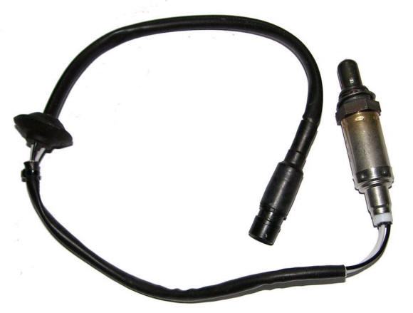
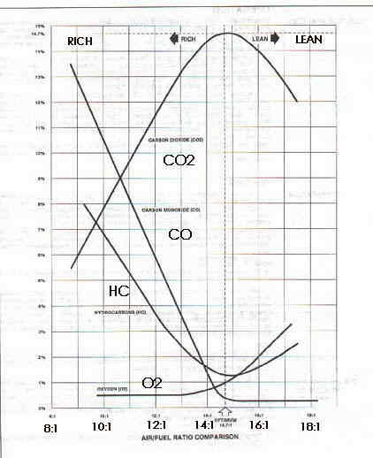
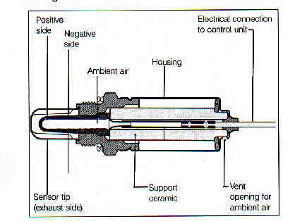
Oxygen Sensors: Why They are Needed and How They Work

The Challenge.

The level of pollutants in exhaust gas must be reduced. While open-loop control systems for ignition and fuel management can improve exhaust emissions, further reduction in emissions is only possible by using catalytic converters. These converters operate efficiently only if unleaded gasoline is used and if combustion is as complete as possible.

The Solution.

To meet the challenge, Bosch developed the oxygen sensor, which has been in series production since 1976. Since then it has been used by vehicle manufacturers in emission control systems which Bosch supplies in the U.S.A., Australia, Europe, Japan, and Korea.

How It Works.

The oxygen sensor is a measuring probe for determining the oxygen content of the exhaust gas. Since the amount of oxygen in the exhaust gas indicates precisely how complete the combustion of the air-fuel mixture in the cylinders is, it is also the best starting point for controlling the. air-fuel ratio. The oxygen sensor is strategically located into the exhaust system. The outside surface of the ceramic measuring tube protrudes into the exhaust gas flow, and the inner surface is in contact with the outside air. A voltage is generated at the interface which is proportional to the relationship between the residual oxygen in the exhaust gas and that of the surrounding air: When this relationship changes, so does the voltage. This voltage is processed by an electronic control unit (ECU) into a control signal for influencing the air-fuel mixture through controllable fuel injection or carburetor systems. The exhaust gas composition is thus always maintained at that level which permits effective after-treatment by the vehicle's catalytic converter.

Design Features.

The ceramic sensor body is contained in a housing which protects it against mechanical effects and facilitates mounting. The ceramic body is made of Zirconium dioxide. Its surfaces are provided with electrodes made of a gas-permeable platinum layer. In addition, a porous ceramic coating has been applied to the side exposed to the exhaust gas. This coating prevents contamination of the electrode surface by combustion residue in the exhaust gas stream for longer service life.

The Advantages.

Feedback from the oxygen sensor provides closed-loop control of the injected quantity of fuel for optimum air-fuel mixture. . . enabling virtually complete combustion to take place. By providing closed-loop control of the mixture, it becomes possible to use three-way catalytic converters to achieve the maximum reduction in exhaust gas emissions. In addition, the engine runs smoother and is more fuel efficient.


Technical Information Oxygen Sensor Diagnosis Generic Method

Here are some fast and reliable diagnostic procedures which you can use to check out most oxygen sensors. A great time to do this is when you are performing a tune-up.

The following symptoms will help tip you off to a failed oxygen sensor:

Surging and/or hesitation
Decline in fuel economy
Unacceptable exhaust emissions
Premature failure of the catalytic converter

You will need the following equipment:

A handheld volt meter (digital VOM)
A propane enrichment device
An oxygen sensor socket
The manufacturer's vehicle specific test instructions.


It should take less than 10 minutes to perform a diagnostic check on most vehicles.

1. Verify the basic engine parameters, per the manufacturer's specifications for the following: timing, integrity of the electrical system (supply voltage), fuel delivery mixture performance and internal mechanical considerations.

2. Treat the rich mixture performance as follows:

a. Disconnect the sensor lead to the control unit.
b. Run the engine at 2500 rpm.
c. Artificially enrich the fuel mixture by directing propane into the intake until the        engine speed drops by 200 rpm. Or, if you're working on a vehicle with electronic fuel injection, you can remove and plug the vacuum line to the fuel pressure regulator.
d. If the voltmeter rapidly reads .9 volts, then the oxygen sensor is correctly sensing a rich mixture. But, if the voltmeter responds sluggishly, or if it stays below .8 volts, then the sensor should be replaced.

3. Test the lean mixture performance as follows:

a. Induce a small vacuum leak.
b. If the voltmeter rapidly drops to .2 volts or below in less than a second, then the oxygen sensor is correctly measuring the lean mixture. But, if the voltmeter responds sluggishly, or if it stays above .2 volts, then the sensor should be replaced.

4. Test dynamic performance as follows:

a. Reconnect the sensor lead.
b. Set the mixture to specification.
c. Run the engine at 1500 rpm.
d. The sensor output should fluctuate around .5 volts. If it doesn't, replace the sensor.

Diagnosis

When performing diagnostic work on your customer's vehicle to determine the cause of a driveability problem or perhaps the reason for failing an emissions test, take the opportunity to check the operation of the oxygen sensor for proper functioning.

Recalling that an oxygen sensor will influence the air fuel mixture preparation only when it has reached proper operating temperature (at least 350oC), it is essential to first ensure that the engine and sensor are warm enough to allow operation in a "closed loop" condition. It may take as long as 2 1/2 minutes after cold start for proper exhaust temperature to be reached (somewhat shorter for heated-type oxygen sensors).

To check the performance of the oxygen sensor, run the vehicle engine at about 2000 rpm (or at normal cruise when working with a dynamometer) to ensure that the sensor remains hot throughout the test procedure. Do not remove or disconnect the sensor lead in order to test it as this will eliminate the "closed loop" signal to the electronic control unit and result in a non-cycling voltage condition. Using a correct electrical impedance test device as found with a laboratory type oscilloscope, connect your test leads so as to read voltage from the signal wire to the electronic control unit. With vehicles that use a heated oxygen sensor (three or four wire), it may be necessary to bridge the connector leads and tap into the signal wire with an appropriate test probe at the connector plug in order to obtain the signal. The oscilloscope will allow you to read the electrical response pattern of the oxygen sensor to changing exhaust gas oxygen content as a measure of its performance.

Before proceeding, be sure that you are using the correct measurement scale for your specific equipment as specified by the test equipment manufacturer. (Invariably, this will be a low voltage scale.)

A properly functioning oxygen sensor will exhibit a rapidly fluctuating voltage signal alternating between approximately .2 and .8 volts in response to varying residual oxygen content in the exhaust stream. Look to your scope's time reference line for a desired lean-to-rich and rich-to-lean time of less than 300 milliseconds. A response time greater than 300ms. means that the sensor should be replaced. It is important to recall that these values are valid only when checking a sensor operating in "closed loop" in a hot exhaust stream (350o-8OOoC). Sensor age degree of contamination, mixture setting, and exhaust temperature all have an effect on response time.

Without this rapid electrical response to changing exhaust composition, the control unit cannot accurately correct the fuel mixture. A sluggish sensor is either contaminated or beyond its intended service life and must be replaced. Additionally, check vehicle manufacturers' service recommendations and suggest replacement of the oxygen sensor at specified intervals.

Oxygen Sensor Installation Tools

In cases where installation position is difficult to access, Bosch recommends using the following tools: OTC 7189 Oxygen Sensor Wrench OR Snap-On 56150 Oxygen Sensor Wrench (Crowfoot type).


What is an Oxygen Sensor?

Are you still wondering what an oxygen sensor actually does?  It exploits a unique fact of combustion technology:  fuel burns most efficiently when an air/fuel ratio is exactly 14.7 to one.  When there's a greater ratio of fuel to air, the combustible mixture is called rich.  When there's a greater ration of air to fuel, the combustible mixture is called lean.  The job of the oxygen sensor is to monitor the combustible mixture to make sure it stays in the perfect ratio in order to lower vehicle emissions and give better fuel economy.  How can it do this?

The oxygen sensor relies on another scientific fact, the "Nernst effect."  Nernst's law gives a way to measure the voltage between two materials in close contact, one of which is a known constant.  When the zirconium dioxide ceramic sensor reaches the high temperatures generated by the car's engine, typically 617 to 662 degrees F, it registers a difference between the oxygen content of outside air (the known constant) and the exhaust gas oxygen content.  This difference is emitted as a voltage signal, proportionate to the difference between exhaust gas oxygen content and that of outside air, and is sent to the ECU (Electronic Control Unit) which measures the electrical switching points of the oxygen sensor voltage as the exhaust gas oxygen content changes. The engine computer reads this signal and adjusts the fuel mixture accordingly in order to maintain the perfect ratio.

So, as the engine runs,  the output voltage changes as the fuel mixtures fluctuates between rich and lean.  The type of engine determines the switching speed of the O2 sensor:  (1) carburetor systems switch 1/second at 2,500 rpm, (2) throttle body injection systems switch 2-3/second at 2,500 rpm, and (3) multipoint injection systems switch 5-7/second at 2,500 rpm.

Oxygen Sensor Problems

Clearly, the O2 sensor will slow with age, contamination or damage, decreasing it's reaction time to changes in the air/fuel ratio.  This may cause higher emissions and greater fuel consumption.

The signs of a failed O2 sensor are:

  • failed emissions test (high CO and/or HC typically)
  • damaged catalytic converter (from an over rich fuel mixture)
  • poor fuel mileage (caused by an over rich fuel mixture)
  • fouled spark plugs (caused by an over rich fuel mixture)
  • the car runs rough and has a sluggish performance.


Oxygen Sensor Problems cont.

Contamination can occur internally from:

  • harmful fuel additives
  • lead
  • silicone (from antifreeze leaking into a cylinder or using the wrong type of RTV sealer)
  • phosphorus (from oil burning)

Contamination can occur externally from:

  • spilled oil
  • overspray of rustproofing or other chemicals
  • water splash can harm non-sealed sensors
  • blockage of air vent hole.

In OBDII systems, an outright failure of an O2 sensor will set a diagnostic trouble code (DTC), but a contaminated or slow sensor might not trigger a code, making diagnosis a challenge.

Replacement Tips

Replacement sensors must be the same basic type as the original (heated or unheated) and have the same performance characteristics and heater wattage requirements.  Installing the wrong O2 sensor could affect engine performance and possibly damage the heater control circuit in the engine computer.

When removing a worn-out sensor, check it for signs of contamination.  Some discoloration is normal, but heavy black deposits indicate an over-rich fuel mixture, dark brown deposits indicate high oil consumption, white or reddish deposits indicate harmful fuel additives, and light colored or grainy deposits indicate a coolant leak.

Bosch replacement sensors have a patented double-layer protection system that provides excellent resistance to exhaust contaminants.  The Bosch patented electrode power grid also contains more platinum than competitive sensors.  Stainless steel laser-welded construction, gold-plated heater contacts, an improved wire seal for all 1-wire sensors, and 100% quality control testing assure reliable, trouble-free operation.

Bosch universal replacement sensors use more part numbers than competitors' universal sensor programs to more closely match OEM requirements.  Bosch offers five different 4-wire sensors and two different 3-wire sensors to provide the closest match to OEM sensor performance.

Bosch also uses a patented connection system that can withstand extreme temperatures, engine vibration and moisture for more than 50,000 miles.  


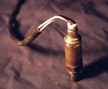
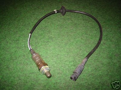
Five Types of Oxygen Sensors

Unheated Thimble-type O2 Sensors (LS)

Bosch introduced this design in 1976 for feedback fuel control on automotive engines. The zirconia ceramic "thimble" is encased in a protective tube which extends into the exhaust manifold.  Slots in the protective tube allow hot exhaust gases to reach the thimble.  Reference outside air for the interior of the thimble comes from a hole in the sensor shell, or through the wiring connector.  Unheated O2 sensors rely only on the heat of the exhaust gases to reach operating temperature, therefore they might cool off while the engine is idling and revert back to a fixed air/fuel ratio setting. This type of sensor generally has a single wire connector, though some have two.

Heated Thimble-type O2 Sensors (LSH)

Introduced by Bosch in 1982, this sensor adds a heater element to the original design so that the sensor achieves operating temperature in 30-60 seconds, instead of being heated by exhaust gases.  It has a separate electric circuit for the heater, so look for 3 or 4 wire connectors to distinguish this unit.  The heater reduces cold start emissions, as well as prevents the sensor from cooling off at idle.

Heated Titania-type O2 Sensors

Titania sensors use a different type of ceramic and instead of generating a voltage signal that changes with the air/fuel ratio, the sensor's electrical resistance changes. The resistance is less than 1000 ohms when the air/fuel ratio is rich, and more than 20,000 ohms when the air/fuel ratio is lean. The ECU provides a base reference voltage and then rmonitors the sensor return voltage as the sensor's resistance changes. Titania O2 sensors are used on less than 1% of O2 sensor-equipped vehicles:

  • '86-'93 Nissan 3.0L trucks
  • '91-'94 Nissan 3.0L Maxima, 2.0L Sentra
  • '87-'90 Jeep Cherokee, Wrangler, and Eagle Summit

Heated Planar-type O2 Sensors (LSF)

Introduced by Bosch in 1997, this O2 sensors uses a laminated flat strip of conductive ceramic, electrodes, insulation, and heater. This sensor is smaller and lighter, and more difficult to contaminate.  The new heater uses less electricity and brings the sensor to the proper temperature in 10 seconds.  Outside reference air is supplied by a small port in the center of the ceramic strip where the 4 electrical wires connect. By model year 2004, planar O2 sensors are expected to account for 30% of all O2 sensor applications and by 2008, for up to 75%. The following list shows the inclusion of more and more models:


Heated Planar-type O2 Sensors (LSF) cont.
  • 1998: VW 2.0L New Beetle
  • 1999: Cadillac Catera, Saturn 3.0L LS, VW 2.0L Jetta
  • 2000: All Audis exc. A4 1.8L turbo and A6 2.8L; California Dodge 2.0L Neon; Ford 4.0L and 5.0L Explorer; Ford 2.5L LEV Ranger; Ford 3.8L Windstar; MBZ 3.2L ML320 and 4.3L ML430; Mercury 4.0L & 5.0L Mountaineer; Saab 2.0L & 2.3L; and all VW and Volvo models
  • 2001: Porsche 911 3.6L Turbo; all MBZ models exc. SL500 and SL600
  • 2002: All Audis, All Dodge Neons, all Ford F-Series trucks (4.2L, 4.6L, 5.4L), all Ford Ranger trucks, Mazda B-Series pickups (2.5L, 3.0L & 4.0L), all MBZ models and Saturn 3.0L SUV

Heated Wide-Band O2 Sensors (LSU)

(from the November 2001 Bosch Reporter)

The newest O2 sensor technology from Bosch builds upon the planar design and adds the ability to actually measure the air/fuel ratio directly for the first time.  Instead of switching back and forth like all previous sensor designs, the new wide-band O2 sensor produces a signal that is directly proportional to the air/fuel ratio.

The wide-band sensor uses a "dual sensing element" that combines the Nernst effect cell in the planar design with an additional "oxygen pump" layer and "diffusion gap" on the same strip of ceramic.  The result is a sensor element that can precisely measure air/fuel ratios from very rich (10:1) to extremely lean (straight air).  This allows the engine computer to use an entirely different operating strategy to control the air/fuel ratio.  Instead of switching the air/fuel ratio back and forth from rich to lean to create an average balanced mixture, it can simply add or subtract fuel as needed to maintain a steady ratio of 14.7:1.

Like a zirconia thimble or planar-type sensor, the wide-band sensor produces a low-voltage signal when the air/fuel ratio goes lean, and a high-voltage signal when the mixture is rich.  But instead of switching abruptly, it produces a gradual change in the voltage that increases or decreases in proportion to the relative richness or leanness of the air/fuel ratio.  So, at a perfectly balanced air/fuel ratio or 14.7:1, a wide-band O2 sensor will produce a steady 450 mv.  If the mixture goes a little richer or a little leaner, the sensor's output voltage will only change a small amount instead of rising or dropping dramatically.

Another difference in the wide-band O2 sensor is the heater circuit.  Like a planar sensor, it is printed on the ceramic strip.  But the heater circuit is pulse-width modulated to maintain a consistent operating temperature of 1292 to 1472 degrees F.  the sensor takes about 20 seconds to reach operating temperature.


Powered by Livedsl